|
|


 Arabic
 Bengali
 Chinese
 English
 French
 German
 Hebrew
 Hindi
Hindi Italian
 Japanese
 Korean
 Malay
Malay Polish
 Portuguese
 Spanish
 Turkish
 Ukrainian
 Vietnamese
|
ENCYCLOPEDIA OF RADIO ELECTRONICS AND ELECTRICAL ENGINEERING Linkwitz frequency response corrector in low-power UMZCH. Encyclopedia of radio electronics and electrical engineering
Encyclopedia of radio electronics and electrical engineering / Transistor power amplifiers The acoustic design of the loudspeakers can be thought of as a high-frequency filter, so there is not only a drop in the amplitude-frequency characteristic (AFC) in the low-frequency region (from 12 to 24 dB per octave), but also a corresponding change in the phase-frequency characteristic (PFC). Depending on the quality factor of the woofer in the acoustic design, there may be a peak in the frequency response (up to 6 ... 8 dB at the resonance frequency of the head in the acoustic design fc), which leads to a "mumbling" sound. The use of a special corrector with a "mirror" characteristic relative to the frequency response of the loudspeaker allows not only to expand the frequency range in the bass region and remove "mumbling", but also to correct the phase response, which favorably affects the fidelity of sound reproduction. The equivalent quality factor of the acoustic system (AS) becomes close to optimal, equal to 0,71. The Linkwitz frequency response corrector (Fig. 1) is an inverting amplifier covered by a frequency-dependent OOS using two double incomplete T-bridges - at the input and in the OS circuit. The input T-bridge is tuned to the frequency fc, in the OS circuit - to the frequency (0,25 ... 0,5) fc.
The elements of the T-bridges are chosen so that the time constants of the Correcting RC circuits τ1 = R1*C2 = R5*C3;
were equal. The gain in the LF region is determined by the ratio KLF = R4/R2. Depending on the quality factor of the woofer in acoustic design, the value of KLF varies within 4,5 ... 15. Obviously, when using a corrector, the UMZCH must have an appropriate overload margin. The quality factor of the T-bridges depends on the resistors R1 and R5. The parameters of the corrector elements for some values of the quality factor of the head in an acoustic system with a phase inverter (FI) are given in Table 1.
The ratings of RC elements must be selected with an accuracy of ±1%. The last column gives the lower frequency of the equalized loudspeaker (relative to the head resonant frequency fs). For other values of frequency fc, the capacitances of capacitors C1 ... C4 are recalculated. For example, the capacitance C1 is: C1' = C1*80 / fc The rest of the containers are calculated in the same way. You can, on the contrary, leave the capacitances the same, and recalculate the values of the resistors R1 ... R6. With a head quality factor of 1,6 and higher, the corrector characteristic has a significant rise at frequencies of 20 ... 30 Hz. In order to avoid overloading the UMZCH at infra-low frequencies, it is advisable to put an additional first-order RC filter at its input with a cutoff frequency of 30 Hz. To understand the operation of the corrector, consider the properties of a double T-bridge (Fig. 2a).
It is a notch filter with a tuning frequency of f0: f0=1 / 2πRC . The depth of rejection (frequency suppression f0) of such a filter reaches 50 dB when operating on a high-resistance load. An incomplete double T-bridge (Fig. 2b) has the same tuning frequency, but the filter quality is much lower, and the notch depth is only 10 dB.
The advantage of an incomplete bridge is that it allows you to tune the filter tuning frequency by changing just one capacitance Cx. The tuning frequency of an incomplete double T-bridge is determined by the formula: f = f0 * n1/2, n = 2 * Cx/C. The depth of rejection of an incomplete double T-bridge for some values of n is given in Table 2.
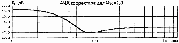
The Linkwitz frequency response corrector is intended mainly for closed acoustic systems, but it can also be used in conjunction with a phase inverter. To determine the quality factor AC Qmc And the resonance frequency fc will require any electret microphone (for example, IEC-3) and a preamplifier with a smooth frequency response in the range from 10 to 10000 Hz. The resonance frequency fc can be determined with an accuracy of 10...15% as follows. The speaker cabinet is sealed by tightly closing the phase inverter hole. The microphone is placed in close proximity (at a distance of 2 ... 2 mm) from the diffuser of the low-frequency head with an offset of 3/0,1 of the diffuser radius from its central axis. A signal with a power of 0,5 ... 20 W is supplied to the speakers. The signal from the output of the amplifier is controlled by a voltmeter and an oscilloscope. By changing the frequency of the generator, the frequency response of the speaker is built from 500 to XNUMX Hz. They are convinced of the presence of a hump in the frequency response in the fc region and a characteristic decay with a steepness of 12 dB / oct. below this frequency. Remove the low-frequency head and determine its main resonance frequency in free space fs and the total quality factor Qts, for example, according to the methods described in [2]. After that, the quality factor of the speaker is determined by the formula: Qmc = Qts *fc/fs. Type of frequency response and phase response of the corrector for Qmc = 1,0 are shown in Fig. 3, frequency response for Qmc = 1,4; 1,8; 2,5 - respectively in Fig. 4 ... 6.
A drawing of a printed circuit board with dimensions of 45x49 mm for a two-channel corrector is shown in Fig. 7, an assembly drawing - in Fig. 8. The board provides places for installing non-polar power decoupling capacitors (they are not shown in the diagram). Chips of the K544UD1 or KR140UD608 type can be used as operational amplifiers.
Considering that the corrector can have a gain at frequencies of 30...40 Hz from 10 to 15 dB (3...5 times), which, when used in a low-power amplifier, will lead to its overload and severe signal limitation, it is necessary to take measures to reduce the visibility distortion. For this purpose, signal limiters (limiters) have recently been increasingly used [3,4, XNUMX]. A possible version of the adaptive limiter is shown in Fig. 9. With the help of resistors R4 and R5, a smooth symmetrical clipping of the signal is achieved, which does not reach a hard limit with a 2 ... 3-fold input overload. Due to the connection of the input divider to the UMZCH power supply, the smooth limitation will be maintained even when the supply voltage changes.
The smoothness of the limiter response depends on the number of diodes and, to some extent, on the input resistors (the larger the resistor value and the fewer diodes, the tighter the clipping characteristic). It is desirable to choose diodes with similar characteristics. A drawing of the printed circuit board of the limiter with dimensions of 52x34 mm is shown in Fig. 10, an assembly drawing - in Fig. 11. As VT1 and VT2, you can use transistors such as KT502E, KT503E, VT3 and VT4 - any low-power complementary ones, for example, KT3102, KT3107. Diodes - any low-power, both silicon and germanium.
Compared to "hard" limiting, when using a limiter, the signal spectrum is enriched with lower order harmonics. However, in this case, at the peaks of the signal, there is a significant decrease in the midrange and high-frequency components and the addition of odd harmonics. To reduce this effect, a corrector combined with a limiter was developed (Fig. 12).
To increase the smoothness of the limitation, instead of increasing the number of diodes, resistors R22 and R23 are introduced, and to reduce the limitation of the midrange and high-frequency components, serial RC circuits are included in dividers R13-R15 (R14-R16). Oscillograms of signals with a frequency of 30 Hz (700 mV) and 1 kHz (175 mV) with a conventional limiter (without dividers) and with the proposed one are shown in Fig. 13 and 14, respectively.
On the oscillogram in Fig. 14, compared to Fig. 13, there is noticeably less suppression of the signal with a frequency of 1 kHz, but phase distortions already appear. Therefore, a compromise has to be found between the degree of preservation of the MF and HF components of the signal and additional phase distortions. The printed circuit board of the device with dimensions of 55x75 mm is shown in Fig.15, and the assembly drawing is in Fig.16.
Literature
Author: A. Petrov, Mogilev; Publication: radioradar.net
Machine for thinning flowers in gardens
02.05.2024 Advanced Infrared Microscope
02.05.2024 Air trap for insects
01.05.2024
▪ HP EliteOne 800 AiO G5 Anti-peeping All-in-One PC ▪ Chip IR25750L for current measurement
▪ section of the site Fundamentals of safe life (OBZhD). Article selection ▪ article Don't think down the seconds. Popular expression ▪ article What is the continental shelf? Detailed answer ▪ Electrician article. Job description
Home page | Library | Articles | Website map | Site Reviews
www.diagram.com.ua |


 Leave your comment on this article: