|
|


 Arabic
 Bengali
 Chinese
 English
 French
 German
 Hebrew
 Hindi
Hindi Italian
 Japanese
 Korean
 Malay
Malay Polish
 Portuguese
 Spanish
 Turkish
 Ukrainian
 Vietnamese
|
ENCYCLOPEDIA OF RADIO ELECTRONICS AND ELECTRICAL ENGINEERING Seven-band directional HF antenna BMA-7. Encyclopedia of radio electronics and electrical engineering
Encyclopedia of radio electronics and electrical engineering / HF antennas An all-wave antenna, or at least one that works on most of the nine amateur HF bands, is the dream of many shortwavers. The task of creating a multi-band antenna becomes much more complicated when it comes to a directional antenna. An interesting solution to it is proposed in the published article. The ideas used by UT1MA in this design may be useful for shortwavers in their own development of KB antennas. Multi-band directional "wave channel" antennas for amateur radio communications are very popular, they are produced by dozens of companies in many countries. Such antennas are mainly made using separating resonant circuits - TRAP, or ladders [1, 2]. Despite the obvious conveniences, this technology is rarely used in amateur antenna design, which is explained, first of all, by the complexity of handicraft manufacturing of a reliable and finely tuned ladder. Recently, antenna designs have appeared in which the problem of multi-band operation is solved in a simpler way, using the so-called multi-band load circuits (LOad Multiband or LOM for short). The main element of such an antenna is a coil with a certain inductance, located in a certain place of the active or passive element. The mechanism of action of the LOM load is that at relatively high frequencies, the coil causes a significant reflection of the current, as a result of which its distribution on the "pre-coil" part is close to the distribution in a conventional dipole with a shoulder length of approximately 0,25λ. At low frequencies, the current propagates along the entire length of the antenna arm and the coil works as an extension coil [3]. Let's try to compare the main parameters of two three-band dipoles: with ladders and with LOM coils. Calculations were made using the MMANA antenna program (TNX JE3HHT and DL2KQ for excellent program). Figure 1a shows a drawing of a dipole for the ranges of 10, 20 and 40 meters. The arms of the dipole are symmetrical, which makes it possible to show only half of the dipole to simplify the figure. We proceed from the fact that the trap capacitors L1C1 (resonance frequency f1 = 28,3 MHz) and L2C2 (f2 = 14,15 MHz) are formed by tubes located inside and outside the coil. Note that this technologically convenient design of capacitors has a significant drawback - due to the influence of these tubes, the quality factor of the coils (and the circuit as a whole) decreases by 3 ... 4 times and in many models does not exceed Q = 80 ... 100. Accordingly, losses in the circuits and their heating increase by the same amount. We accept C1 = 25 pF, C2 = 15 pF, Q1 = 100 and Q2 = 80, and the diameter of the antenna conductor (tube) is 30 mm. The dipole sections ab, cd, eg have lengths at which the reactive component of the input resistance is close to zero in all three ranges.
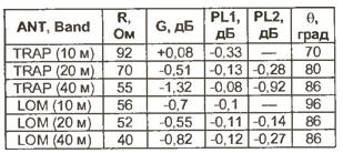
Diagrams of the change in the magnitude of the current along the dipole in different ranges are shown in Figs. 1b (range 10 meters), fig. 1,c (20 meters) and fig. 1, g (40 meters). The arrows at the diagrams show the direction of the current in the corresponding parts of the dipole. MMANA shows that there is also a small current on the parts of the dipole located behind the ladders, which appears as a result of interference from the working area of the antenna. On a range of 10 meters, this current significantly, by about 0,4 dB, increases the antenna gain by narrowing the radiation pattern (DN) and also increases the input impedance of the antenna. The calculation results are summarized in the table. In it, R is the input impedance of the antenna at resonance. The gain G is given with respect to a half-wave dipole without traps. Separately, the total heat losses in two coils PL1 and two PL2 are highlighted, since the reliability of the antenna directly depends on these losses. G is the width of the main lobe of the pattern at -3 dB, or 0,707 of the maximum. When estimating heat losses, it can be assumed that 0,1 dB corresponds to approximately 2,4% of the total power. The total length of the dipole is 2x6,7 m. On fig. 2, and also shows a dipole for the ranges of 10, 20 and 40 meters, but, unlike the first one, it does not use ladders, but LOM coils. The values L1 and L2, the lengths of sections ab, cd, eg and capacitive loads EH1 and EH2 are chosen so that the reactive component of the input resistance is close to zero in all three ranges. In particular, the length of the first section ab will then be about 0,25 wavelength for a range of 10 meters. Due to the presence of L1 in this range, the shape of the current curve in section ab is almost the same as that of a half-wave dipole.
The current behind the coil in the section cd is several times less than in the first section. This is important, since here the current has the opposite direction and its action leads to the expansion of the RP and, accordingly, to a drop in the dipole gain. To minimize this undesirable effect, a capacitive load EH1 is introduced, which "takes over" and excludes part of the counter current from the radiation. The magnitude of the current in the section cd also depends on the inductance of the coil L1 and will be the smaller, the larger it is. On the other hand, increasing the inductance of the coil leads to a decrease in the bandwidth on the second band (20 meters), so the choice of the inductance of this coil is an inevitable compromise. On a range of 20 meters, the L2 and EH2 elements work in a similar way, and the L1 coil works as an extension coil. On 40 meters both coils are extension coils. Diagrams of currents along the conductor of this version of the dipole are given in fig. 2,6 (10 meters), fig. 2,c (20 meters) and fig. 2, g (40 meters). The calculation showed that the optimal values would be L1 = 3,5 µH and L2 = 18 µH. The total length of the dipole is 2x5,8 m with a tube diameter of 20 mm in the extreme section and 30 mm in the rest. The length of EH1 is 0,8 m and EH2 is 0,6 m, the tubes are 16 mm in diameter. The calculated parameters are also given in the table, which is convenient for comparison. In the calculations, the quality factor of the coils L1 and L2 is taken to be 250, which is quite realistic.
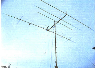
Comparison of thermal losses in TRAP and LOM dipoles shows that the second loss is 2...3 times less. Under the same other design conditions, the LOM antenna is able to withstand more power. However, if external capacitors are used in the traps, both types of antennas will be approximately equal in this indicator. A useful property of the LOM antenna is its non-criticality to the value of the inductance of the coils. If it deviates from the calculated value by 10%, the resonant tuning is easily restored by adjusting the length of the EH elements. In this case, the antenna parameters change insignificantly. There is also an obvious advantage - there is no need to use high-voltage capacitors designed for high reactive power. After successfully using LOM technology in a vertical multiband antenna [3, 4], the author made an attempt to apply this technology in an active vibrator (AB) of a simple directional antenna for seven KB bands - from 10 to 40 meters. AB is designed to use one 50-ohm feeder without any switching. In addition to the AB, the antenna includes five reflectors in the ranges of 10, 12, 15, 17, 20 meters, and on the bands of 30 and 40 meters, only an active vibrator works in the antenna. The appearance of the experimental antenna, which received the author's name BMA-7 (Beam Multiband Antenna for 7 bands), is shown in fig. 3.
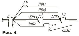
Schematically, the electrical circuit of its active vibrator is shown in fig. 4. Each arm AB (conditionally shown only one of the two) consists of four conductors, the beginnings of which converge at the feed point.
The structural basis of the antenna is a central vibrator, consisting of three segments of duralumin pipes, between which there are coils L1 and L2. This vibrator operates on 10, 20 and 40 meters. Ranges of 15 and 17 meters are provided by wire vibrators PV15 and PV17. The L4 coil with a small inductance makes it possible to reduce the length of the PV17 vibrator to the dimensions required for design reasons. The PV12 vibrator works in the range of 12 meters, and together with the L3 coil and the additional conductor PVZO, a 30-meter range emitter is obtained. Naturally, there are mutual influences between the components of the AB, but nevertheless, in general, clear seven resonances and SWR are obtained at medium frequencies of all ranges within 1,1 ... 1,4 (only AB - without reflectors). A more detailed drawing of AB with the main dimensions in two projections is schematically shown in fig. 5.
Wire vibrators PV are made of stranded wire in vinyl insulation of the PVZ brand with a cross section of 2,5 square meters. mm. To support the wire vibrators, small nut insulators IO and plastic antenna insulators IE of the company "Antennopolis" (Zaporozhye) were used. These insulators are 17x17x115mm and have four holes - two at the edges and two in the middle. The L4 coil has 7 turns and is wound directly on the middle part of the insulator from the PV17 emitter wire. Wire emitter PV12 is fixed at some distance from the central vibrator by dielectric spacers RP. The far (from the center of the antenna) ends of the PV15 and PV17 emitters are fixed through polypropylene stretch marks PP on the EH2 tube. The 10-meter range reflector is made of a tube with a diameter of 20 mm and has a length of 5,3 m, the 15-meter range - from tubes with diameters of 30, 20, 16 and 10 mm (total length 7,235 m), the 20-meter range - from tubes with diameters of 30 and 20 mm (total length 10,51 m). The distances from AB to the reflectors of the ranges of 10, 15 and 20 meters are 2,05, 2,6 and 3,7 m, respectively. The reflectors of the 12 and 17 meters ranges are made of stranded wire in vinyl insulation of the PVZ-2,5 brand and are located respectively above the reflectors of 15 and 20 meters (see Fig. 3) in such a way that the middle part of the wire reflector is 0,5 m higher than the tube reflector , and the ends at 0,2 m. The total length of the reflector of the range of 12 meters is 5,5 m, the range of 17 meters is 7,75 m. Capacitive loads are from a tube with a diameter of 16 mm, the length of EH1 is 1,3 m and EH2 is 1,6 .1 m. Coil data: L33 - frame with a diameter of 1 mm, MGTF wire with a cross section of 9 sq. mm, number of turns - 2, tight winding, waterproofing with NOVA ROLL electrical tape; L32 - frame with a diameter of 0 mm, MGTF 75 sq. mm, number of turns - 24; L3 - frame with a diameter of 40 mm, MGTF 0,75 sq. mm, 18 turns. The antenna was experimentally tested first on a mock-up, and then a real sample was brought up. The active vibrator was tuned using a bridge SWR meter: on the ranges of 10 and 20 meters by changing the length of the capacitive loads, and on the range of 40 meters by changing the length of the end section. The remaining ranges are adjusted by selecting the lengths of wire vibrators. It was difficult to calculate the length of the wire reflectors due to the presence of vinyl insulation on the wire and the proximity of the tube reflectors; they were tuned using the GIR to a frequency that differed from the average frequency of this range by 3% down. The total length of the active vibrator is 2x6,35 m. After receiving the MMANA computer program, the calculation of the active vibrator (ranges of 10, 20 and 40 meters) showed how the same parameters can be obtained by reducing the lengths of EH and the total length of the active vibrator (see the calculation data above). The power cable is matched with the AB using only one additional element - a capacitor with a capacity of 56 pF / 2,5 kVA, connected in parallel to the antenna input. Balancing is carried out using a protective choke L5 of 15 turns of the coaxial cable of the RG-58 feeder, wound on an annular ferrite magnetic core with a diameter of 65 mm made of 300VN material. The inductor and the matching capacitor are placed in a protective casing and mounted on a steel strut RP1 in the center of the AB, supporting the elements PV15 and PV17. It should not be forgotten (when modeling an antenna, in particular) that the wire segments going to the transformer (about 10 cm long each) are included in the electrical length AB. The central part AB (up to coils L2) is made of a tube with a diameter of 30 mm, and the end segments are made of tubes with a diameter of 20, 18 and 10 mm, inserted one into the other. The antenna is powered by a PK50-7 cable 30 meters long. After a slight correction of the lengths of the AB elements, the following values were obtained: SWR - at medium frequencies of the ranges within 1,1 ... 1,4; the operating frequency band for SWR ≤ 2 is 10 MHz on the band of 1 meters, 12 MHz on the bands of 15, 17 and 0,5 meters, 20 MHz on the band of 0,32 meters, 30 MHz on the band of 0,09 meters and on in the range of 40 meters - 0,18 MHz. The measurements were carried out with a DRAKE WH7 instrument. Checking the antenna "on the air" showed that the forward / backward ratio on medium routes on a range of 20 meters lies within 12 ... 15 dB, on the upper ranges - 15 ... 18 dB. On 40 meters when compared to the Inv. V, it turned out that in the direction of its maximum radiation, the BMA-7 antenna was not inferior to the full-sized Inv. V, but in the lateral direction it exceeded by 1...2 points. The calculated values of the gain in the ranges of 10...20 MHz are 4...4,5 dBd. Is it possible to improve the parameters of this antenna by adding directors? This is quite difficult for the following reasons. Firstly, the directors of the lower ranges significantly worsen the parameters of the upper ones. To eliminate this phenomenon, it will be necessary to introduce ladders, LOM-coils or take other special measures. Secondly, it will be difficult to use standard matching methods with one feeder due to the spread of input resistances on different ranges. Perhaps, it is in the form described that the antenna may be of interest to the "average" shortwave. In terms of its parameters, the BMA-7 antenna is close to a log-periodic antenna 6 ... 8 meters long, but it has elements for 30 and 40 meters. It can also be noted that among Western shortwaves, a simple FORCE-4 C12 antenna with a boom length of 3,6 m is popular, having two elements each on the bands of 10, 15, 20 meters and one on the band of 40 meters with two feeders (the price is about $700). In conclusion, we can say that, as shown by this work, LOM technology can be successfully applied in multiband antennas, competing on equal terms with TRAP technology. The author would like to thank Boris Kataev (UR1MQ) for his invaluable help during the installation and tuning of the BMA-7 antenna. Literature
Author: E.Gutkin (UT1MA), Lugansk, Ukraine
Machine for thinning flowers in gardens
02.05.2024 Advanced Infrared Microscope
02.05.2024 Air trap for insects
01.05.2024
▪ Graphene laser for photonic microcircuits ▪ Hardware Optimization Reduces 5G Power Consumption ▪ Multimedia complex Ford Sync 3
▪ section of the site Note to the student. Article selection ▪ Olympian article. Popular expression ▪ article Which country first had a flag? Detailed answer ▪ Article Special clothing and personal protective equipment ▪ article Simple tachometer. Encyclopedia of radio electronics and electrical engineering ▪ Article Tambourine. Focus Secret
Home page | Library | Articles | Website map | Site Reviews
www.diagram.com.ua |


 Leave your comment on this article: