|
|


 Arabic
 Bengali
 Chinese
 English
 French
 German
 Hebrew
 Hindi
Hindi Italian
 Japanese
 Korean
 Malay
Malay Polish
 Portuguese
 Spanish
 Turkish
 Ukrainian
 Vietnamese
|
ENCYCLOPEDIA OF RADIO ELECTRONICS AND ELECTRICAL ENGINEERING New antenna amplifiers. Encyclopedia of radio electronics and electrical engineering
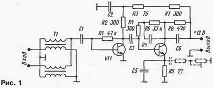
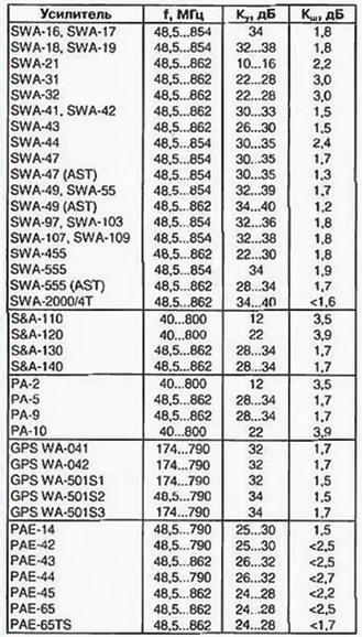
Encyclopedia of radio electronics and electrical engineering / Antenna amplifiers In the 90s, in connection with the expansion of the on-air television network and the increase in the number of active channels, user interest in multi-channel television antennas, capable of receiving axis programs in the MB and UHF bands, without any switching, sharply increased. Since the middle of the decade, Polish small-sized television antennas ASP-4WA, ASP-8WA (CX-8WA) from ANPREL, DIPOL, ELECTRONICS and others began to enter the market, satisfying (to one degree or another) the requirements of such reception. Antennas quickly gained popularity, and quite a large number of them are now in operation. Individual television antennas ASP-4WA, ASP-8WA are flat vibrator structures with a common mesh reflector screen. They are active, that is, they are equipped with electronic amplifiers installed directly on the antennas and powered by a drop feeder. Many characteristics of antennas, such as, in particular, gain and bandwidth, are obtained through the use of antenna amplifiers. Consequently, the quality of the reproduced television image largely depends on the parameters of the latter. For active ASP antennas, different manufacturers produce a whole range of unified antenna amplifiers under various brands and numbers. Structurally, they are all designed in the same way: in the form of a small printed circuit board (approximately 60x40 mm) with surface-mounted microelements. The boards are manufactured using automated SMD technology and are quite reliable due to repeated control. Due to their characteristic design, these antenna amplifiers are called plate amplifiers. The circuitry, parameters, shortcomings and repair of a large number of SWA antenna amplifiers are described in detail in [1]. However, the companies that produce such amplifiers are improving their products, and many new models have now appeared: SWA. S&A, GPS, PAE, etc. Their parameters are undoubtedly of great practical interest both for owners who already operate antennas and want to improve image quality, and for those who decide to buy a new antenna. In addition, amplifiers can work with other types of antennas, for example, log-periodic, wave channel, etc. (provided that the input impedances are matched). Antenna amplifiers have a number of characteristic parameters, which can be conditionally divided into two groups: general and individual. The general ones include: input and output resistances (300 and 75 Ohms, respectively), supply voltage (9 ... 15 V at nominal 12V), operating frequency-channel interval (1-68 TV channels, with rare exceptions). Thanks to the common parameters, the interchangeability of amplifiers is ensured. However, to assess the quality of an amplifier, individual parameters that distinguish one amplifier from another, in particular, noise and amplification, are also important. Information about them is not always available, although recently it has been partially placed in the sales documentation for antennas. It is fully indicated in company catalogs, which are difficult to purchase even from companies that sell antennas in bulk. In order to choose the right antenna amplifier, it is necessary to know two of its individual parameters: the noise figure and the reduced gain Ku. It is also highly desirable to represent the type of its frequency response. Of paramount importance when choosing an amplifier is the noise figure: it should be as small as possible and certainly lower than that of the input stage of the TV [1]. A modern antenna amplifier should have a noise figure of no more than 2 dB. The second parameter (gain) is calculated according to the method described in [1], based on signal losses in the cable and passive splitters (if any). The antenna amplifier is selected according to the closest to the calculated value of the coefficient Ku. Its increase in excess of the calculated one gives an effect while reducing the noise level, otherwise the danger of self-excitation and overloading the amplifier with powerful signals from nearby stations only increases. It is also necessary to take into account the dependence of the coefficient Ku on the frequency, which is determined by the actual frequency response of the amplifiers. Each of them has its own characteristic form of the frequency response. So, the SWA and PAE amplifiers have one smooth maximum (hump) at a frequency of approximately 600 MHz (the gain rise reaches 6 ... 10 dB). The S&A and PA amplifiers have a two-hump characteristic: the second gain increase by 3 ... 5 dB is located at a frequency of approximately 100 MHz, i.e., at MB. The type of frequency response allows you to select an amplifier depending on the reception conditions in order to improve stability and noise immunity by reducing the gain in non-working parts of the range. The gain specified in the documentation, as a rule, refers to the DM V range, at MB frequencies it can be significantly lower. Most of the new amplifiers are assembled according to the traditional two-stage OE-OE scheme. Consider the circuitry, parameters and frequency response of some new models of amplifiers of various brands. Amplifier SWA-555, the schematic diagram of which is shown in fig. 1 is a two-stage aperiodic RF amplifier based on T67 (BFG-67) or BFR-91A bipolar microtransistors.
The first stage is broadband, without correction. There is a correction in the second stage: capacitor C5 in the current feedback circuit of the transistor VT2 provides a drop in the frequency response at the lower frequencies of the operating range [1], and capacitor C4 in the voltage feedback circuit limits the gain at high frequencies and outside the operating band. The frequency response of the amplifier is shown in fig. 2.
In general, the circuits of the SWA-555 and SWA-9 amplifiers are almost identical (the first one only lacks an LC filter in the power circuit and some ratings of passive elements have been changed). Therefore, the frequency response of the amplifiers are close. However, when using the BFR-91A low-noise transistor (Ksh = 1,6 dB) in the first stage, the SWA-555 amplifier has a lower noise figure. S&A amplifiers have more complex equalization circuits in both stages. In models S&A-130, S&A-140, the schematic diagram of which is shown in fig. 3, a serial circuit L1C1 is introduced into the OOS circuit for the voltage of the cascade on the transistor VT2. Its resonant frequency is chosen such that the gain of the first stage decreases at the upper frequencies of the range, which contributes to the stability of the amplifier. To expand the correction band, the quality factor of the L1C2 circuit is reduced by resistors R1, R3. which provide the necessary constant current base of the transistor VT1.
The second stage is equipped with double RC circuits R6, R7, C6 and R7, C4, C5 in the emitter circuit of the transistor VT2, which change the frequency response in the low-frequency region. As a result, the characteristics of the amplifiers are double-humped, as shown in Fig. 4.
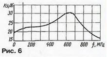
The increase in gain at a frequency of 100 MHz reaches 3...4 dB. The gap between the humps falls on the frequencies of 230...400 MHz, which are not used by terrestrial television channels. This form of frequency response improves the stability and noise immunity of the amplifier. Other features of the S&A amplifiers include the use of a lightning protection diode VD1 at the input. Its efficiency is not very high, so it is recommended to ground the antenna. In PAE amplifiers, as in S&A, LC correction is applied in both stages. In the RAE-45 amplifier, the circuit diagram of which is shown in fig. 5, it is provided by two serial circuits L1C3 and L2C5, included in the OOS circuits for the voltage of the first and second stages, respectively.
In addition, affect the formation of the frequency response and capacitors C2, C8. As a result, the hump on the frequency response of this amplifier is sharper, with a sharp drop at frequencies above 700 MHz, as can be seen in Fig. 6.
It makes no sense to consider PA amplifiers in detail, since they are similar to S&A amplifiers, with the exception of using a coil instead of a VD1 diode at the input. The frequency response of the RA and S&A amplifiers is approximately the same. The GPS models are similar to the SWA-455, SWA-555 amplifiers and differ only in the values of the corrective elements in the second stage. By increasing the capacitance of the blocking capacitor in the emitter circuit of the second transistor, an increased gain was achieved in the frequency range of 100...400 MHz. In some new models of amplifiers, an additional circuit is connected to the emitter of the second transistor from series-connected tuning and constant resistors and a capacitor (shown in Fig. 1 by a dashed line). In this case, the trimmer resistor can change the gain in the lower frequency range and, consequently, the frequency response of the amplifier. Unfortunately, the value of such a correction regulator is small, since the amplifier is difficult to access when the antenna is raised. The analysis of the circuitry and frequency response, of course, is not complete, since, in addition to corrective circuits, the frequency response is affected by the relative position of parts, mounting capacitance, the presence of strip lines, etc. Nevertheless, according to the author, it is sufficient for the correct choice of amplifier by type of frequency response, and in some cases for self-tuning by selecting corrective elements. The following practical recommendations emerge from the analysis. The real form of the frequency response of the SWA and PAE amplifiers is such that they are best used mainly for receiving remote stations in the UHF range. at which the amplifiers have maximum gain. Due to the reduced gain in the MB region, such amplifiers (especially PAE) are more stable and better protected from interference at these frequencies. To receive weak MB signals, preference should be given to S&A, PA and GPS amplifiers, which have increased gain on the MB. This is especially important, given that small-sized ASP antennas have very low intrinsic gain on the MB band: at a frequency of 50 MHz, for example, for the ASP-8WA antenna, it does not exceed 1 dB [2]. Main parameters of new SWA models. S&A. PA, GPS, PAE (operating frequency interval f, noise figure Ksh and gain factor Ku) taken from the Internet [2], as well as from company catalogs, are presented in the table placed here. In case of discrepancies in information, the worst values are included in it. Obviously, some new models have achieved some noise reduction (up to 1,5 dB), however, there are still quite "noisy" amplifiers with NR1 equal to 3 ... 3.9 dB (SWA-31. SWA-32, S&A- 110. S&A-120. RA-10), which are not recommended.
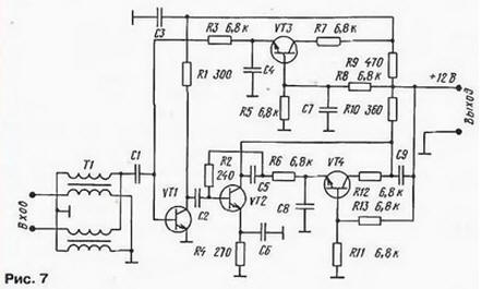
Manufacturers have not yet managed to achieve a significant improvement in the noise characteristics of most amplifiers. The best previous models SWA-7, SWA-9 had a Ksh = 1,7 dB [1]. It remained approximately the same for new amplifiers or was slightly reduced, with the exception of the SWA-47(AST), SWA-49(AST) models. This is primarily due to the fact that the circuitry and transistors used have not changed: the same microwave transistors T67, V3, 415 with a limiting frequency of 7,5 GHz and a noise figure of up to 3 dB [2] are used in the input stages, and only occasionally - less "noisy BFR-91A. It should be noted that the characteristics of the amplifiers are affected not only by the type of the first transistor, but also by the operating mode. The level of intrinsic noise, the gain and the value of the active component of the input conductivity, which affects the degree of input matching, depend on its collector current. In most antenna amplifiers, the transistor VT1 operates at a collector current of 1 "= 8 ... 12 mA. This allows you to get a fairly high gain and good matching with the input transformer T1, but it is not optimal for ensuring a low level of intrinsic noise. Although the dependences Ksh \u2d f (Ik) microchips used are unknown, but, as a rule, for bipolar silicon microwave transistors, the minimum noise level is observed at a collector current of 5 ... 3 mA [1]. noise while maintaining good matching at the input. This is indirectly confirmed by the fact that for PAE amplifiers (only for them) the current of the first transistor is reduced to 4 ... 5 mA. Due to which, with the same transistors, a significant reduction in the noise level was achieved: according to information from Internet networks, the Ksh coefficient for these amplifiers reaches 0.8 ... 1 dB. As noted in [1], many high gain SWA antenna amplifiers are prone to self-excitation. This is explained by. that it is quite difficult to ensure the stability of a two-stage aperiodic RF amplifier assembled according to the OE-OE scheme in the frequency band up to 900 MHz. It would seem that a further increase in the number of cascades does not make sense, since it is practically impossible to achieve stability in this case. Nevertheless, amplifiers assembled on four transistors appeared on the market. Intrigued by this fact, the author purchased the SWA-2000/4T amplifier. Its circuit diagram, drawn up on a printed circuit board, is shown in fig. 7.
An analysis of the circuitry of this amplifier showed that it was assembled according to the usual scheme on two transistors VT1 and VT2, connected with an OE. The input signal is fed to the base of the transistor VT1, amplified in a two-stage track and removed from the collector of the transistor VT2. acting through the transition capacitor C9 in the coaxial cable. Additional transistors VT3 and VT4 are included in the active circuits that set the bias voltage at the bases of transistors VT1 and VT2. Since transistors VT3, VT4 do not amplify the useful signal, low-frequency and cheap 3F chips are used for this purpose. Obviously, with such a construction, the characteristics of the SWA-2000/4T amplifier cannot in any way significantly exceed the parameters of two-stage amplifiers with similar correction (SWA-7, SWA-9, SWA-555, etc.), which was confirmed by comparative tests. Summarizing, we come to the following conclusions. Firstly, many of the new amplifiers repeat the circuitry and, accordingly, the characteristics of the old models. At the same time, a solid number of a new development does not at all indicate its higher quality. For example, the SWA-555 amplifier in terms of parameters and circuitry is the same SWA-9 amplifier. The same applies to amplifiers assembled on four transistors. Secondly, among the new amplifiers there are models with really improved characteristics, which also implies the possibility of improving the quality of reception. In terms of noise parameters, the SWA-47 (AST), SWA-49 (AST) amplifiers can be recognized as the best, and also, judging by information on the Internet, PAE-type amplifiers. Thirdly, the replacement of the antenna amplifier will lead to a positive effect only if a new model with a lower noise level, the calculated gain value and a suitable frequency response is used. In conclusion, let's say that manufacturers develop models of antenna amplifiers quite quickly and it is possible that by the time the magazine with this article is published, new, improved amplifiers will probably appear. In any case, the criteria for determining their quality and recommendations for selection, considered here and in [1], do not change. Literature
Author: A.Pakhomov, Ph.D. tech. Sciences, Zernograd, Rostov region
The existence of an entropy rule for quantum entanglement has been proven
09.05.2024 Mini air conditioner Sony Reon Pocket 5
09.05.2024 Energy from space for Starship
08.05.2024
▪ New opportunities for overclocking 7nm chips ▪ Only five genes determine a person's face ▪ Samsung has released the first mobile phone with a hard drive ▪ Material that restores nervous tissue with electrical impulses
▪ site section Acoustic systems. Article selection ▪ article by Isocrates. Famous aphorisms ▪ article plumber. Job description
Comments on the article: Leo Reduce the power to 5 volts and the noise will decrease.
Home page | Library | Articles | Website map | Site Reviews
www.diagram.com.ua |


 Leave your comment on this article: