|
|


 Arabic
 Bengali
 Chinese
 English
 French
 German
 Hebrew
 Hindi
Hindi Italian
 Japanese
 Korean
 Malay
Malay Polish
 Portuguese
 Spanish
 Turkish
 Ukrainian
 Vietnamese
|
ENCYCLOPEDIA OF RADIO ELECTRONICS AND ELECTRICAL ENGINEERING VHF antennas from a set of typical elements. Encyclopedia of radio electronics and electrical engineering
Encyclopedia of radio electronics and electrical engineering / VHF antennas Radio amateurs conducting experiments with receiving television antennas will be able to more easily realize their ideas if they have a constant set of typical antenna elements - a single constructive basis. Such a set is proposed here. The author also considers several options for antenna designs. Using a single structural basis, i.e. the same materials and basic structural elements, it is possible to manufacture antenna devices of various types, purposes and operating frequency bands. This will allow you to quickly assemble them, change them constructively, measure and compare various electrical parameters. The elements (blanks-materials) of the proposed unified structural basis for antennas operating mainly in the UHF range are shown in Fig. 1. It contains a block 1 with dimensions 44x22x14 mm made of duralumin, an insulator 2 with dimensions 30x24 mm and a thickness of 1...4 mm made of fiberglass, a pipe 3 with an outer diameter of 14...18 mm made of duralumin (for example, a ski pole), strip 4 of duralumin with a width of 22 and a thickness of 2.. 6 mm. bar 5 with a diameter of 3,57 ... 8 mm from an aluminum core of an electrical cable (1) and a mount 6. The latter consists of a duralumin sleeve, a steel angle, fasteners and ensures the installation of an antenna on a mast or vertical bracket with a diameter of 12 ... 50 mm. Elements can be modified depending on the requirements for a particular design: make threaded or non-threaded holes in the block or insulator, press (flatten) the ends of the bar and make holes for screws, etc.
Consider the features of various types of antennas assembled using structural basis elements, using the example of television receivers. On fig. 2 shows a double zigzag antenna (DZA) UHF. Its strength elements are the upper 1 and lower 9 traverses from the pipe and the jumper 2 from the strip 6 mm thick. The jumper is located along the line of zero potentials and does not affect the electrical parameters of the DPA. Active vibrator 4. broadband loop reflector 5 with a shunt 6 (2] made of a rod and jumper 2 are connected to traverses 1 and 9 by four mounting blocks 8. For this purpose, M4 threaded holes are made in the blocks before assembly (MZ-M6 can be) Active vibrator 4 protected from deformation by an insulator 7.
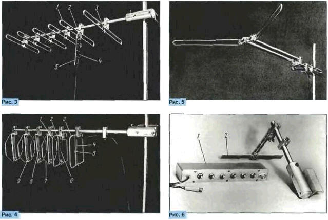
The upper traverse 1 is fixed with a screw 11 in the mount. Consequently, both the deformation of the traverse wall during clamping and the loss of the traverse when the screw is loosened are excluded. For electrical installation of DZA, cable RK75-2-13 was used. petals made of tinned copper wire with a diameter of 1,4 ... 1.7 mm and brackets made of tinned copper or aluminum wire of the same diameter. The cable is connected to the contacts on the insulator 3. The drop cable is connected to the same contacts "under the screw". The immobility of the drop cable at the connection point is provided by block 10. The vertical size of vibrators 4 and 5 between the axes of the mounting holes is 322 mm. The distance between the vibrators is about 100 mm. DZA weight without attachment point -0,5 kg. Weight of the mount - 0.3 kg. On fig. 3 shows the antenna "wave channel" (AVC) for UHF. The AVK vibrators are made of a rod and resemble a loop vibrator in shape, however, only the active vibrator 1 serves as such, since there is an insulator 2 in the gap of the lower conductor. Each of the passive vibrators is closed by a spacer 3 from the strip. The material of the vibrators works in tension and compression, which allows it to withstand significant loads in the vertical plane, which can be caused by birds. With this design of the vibrators, the bandwidth and efficiency of the antenna increase due to the larger surface of the conductors. The AVK uses a range balancing device (DSU) [3]. consisting of a quarter-wave short-circuited symmetrical line 5. a quarter-wave open asymmetrical line 4 and a part of the drop cable located on the opposite branch of the symmetrical line. The PK75-4-11 cable is cut and fixed with wire brackets on a quarter-wave line 5. The twisted ends of the cable braid are connected "under the screw" to the contacts on the insulator 2. The copper ends are clamped between steel washers to prevent the formation of an electrogalvanic copper-aluminum pair. The lengths of the vibrators are as follows (from left to right in Fig. 3): 240.250.254.264,286 and 348 mm. The distance between them is 73 mm.
A multi-element loop antenna (MRA) for UHF is shown in fig. 4. Each of the MPA loop vibrators has a stiffening element made of a strip cut on one side, located along the line of zero potentials and performing one more function. In the active vibrator 1, it (2) serves as a quarter-wave line of a range balancing transformer (DST) (4). in the reflector 3, the stiffening element 4 performs the functions of an electrical extension of the reflector and a regulator of its natural frequency by moving when adjusting the contactor 5. In the director 7, the stiffening element 8 serves to change the natural frequency of the director by the contactor 9. The required reduction in the perimeter of the directors is provided by the octagonal shape of the conductors. All stiffening elements have a length of 145 mm. The electrical installation is made with a PK75-2-13 cable. The output resistance of the MPA is 15 ... 20 ohms. therefore, as a quarter-wave resistance transformer 6 in the DST, two parallel cable segments were used to obtain a wave resistance of a quarter-wave transformer of 37.5 Ohm. The perimeter of the reflector and the active vibrator is 536 mm. perimeter of directors - 448 mm. The distance between the elements is 73, 67. 67, 62,101 mm. The mass of the MPA without the attachment point is 0,8 kg. DZA, AVK and MRA allow changing the number of vibrators and the distances between them without dismantling the antennas and without disconnecting the drop cable. The considered examples do not exhaust the possibilities of applying the proposed constructive basis. On fig. 5 shows a weakly directional antenna based on a split vibrator. It works in the intervals of 6-12 and 21-40 TV channels. The angle in the horizontal plane between the halves of the vibrator is 120°. The length of each half of the vibrator is 360 mm. The length of a quarter-wave symmetrical line formed by two pipes with a diameter of 16 mm. equal to 390 mm. Distance between axes of pipes - 60 mm. The cable RK75-4-11, laid inside the pipes, together with the symmetrical line form a DSU (3]. The length of the cable segment in the left pipe is 240 mm. The assembly of each of the described antennas is multivariate. So, for example, in the DZA reflector (Fig. 2) a shunted loop vibrator is used, although it is possible both to remove the reflector and use its flat design with linear horizontal vibrators made of a bar or strip. Another example related to the same DZA. Vertical jumper 2 in fig. 2. serving as part of the power "skeleton" of the structure, made of a strip 6 mm thick. If it is made of a material with a thickness of 2 mm, then the rigidity can be increased, and the mass can be reduced compared to the original version by using two identical jumpers. One of them is installed, like jumper 2. and the second is attached to opposite planes of the pads parallel to the first jumper. In this case, a three-dimensional stiffening element is formed instead of a flat one. Installation on MPA vibrators (Fig. 4) of shunts similar to shunt 6 in the DZA reflector (Fig. 2). expands the operating range of the MRA towards low frequencies, and a decrease in the perimeter of the loop vibrators due to a change in shape with the same coordinates of the mounting holes shifts the operating range to the region of high frequencies. The structures described above are intended for outdoor installation. By expanding the structural basis with a plastic or wooden support and using a semi-finished product used for the block, one can assemble one of the modifications of the UHF two-band antenna [3. 5], designed for indoor use. The choice of the type of antenna in the absence of measuring instruments is reduced to an assessment of the quality of reception provided by the antenna using a television test table. For a comparative quantitative assessment of the results, a step attenuator 1 is used [6]. shown in fig. 6. Normalized attenuator resistance -75 Ohm. ultimate attenuation - 63 dB. resolution -1 dB. number of stages - 6. Each stage is located in a separate shielding compartment of the housing. The electrical parameters of the assembled antennas are compared with the parameters of the auxiliary antenna 2 in fig. 6. When measuring with a step attenuator, the TV is used as a threshold device. In this regard, there is no need to open the TV and interfere with its circuits. An objective indicator of reaching the threshold level of the signal is a change in the synchronization of the sweeps. Literature
Author: A. Trifonov, St. Petersburg
Machine for thinning flowers in gardens
02.05.2024 Advanced Infrared Microscope
02.05.2024 Air trap for insects
01.05.2024
▪ Insulated Gate Bipolar Transistor FGA25N120ANTD ▪ New solar panel efficiency record
▪ site section And then an inventor (TRIZ) appeared. Article selection ▪ article From board to board. Popular expression ▪ article Which city holds the world record for the most bridges? Detailed answer ▪ article Barman. Standard instruction on labor protection ▪ article FET Distortion Effect Devices. Encyclopedia of radio electronics and electrical engineering
Home page | Library | Articles | Website map | Site Reviews
www.diagram.com.ua |


 Leave your comment on this article: