|
|


 Arabic
 Bengali
 Chinese
 English
 French
 German
 Hebrew
 Hindi
Hindi Italian
 Japanese
 Korean
 Malay
Malay Polish
 Portuguese
 Spanish
 Turkish
 Ukrainian
 Vietnamese
|
ENCYCLOPEDIA OF RADIO ELECTRONICS AND ELECTRICAL ENGINEERING Shortened VHF antenna. Encyclopedia of radio electronics and electrical engineering
Encyclopedia of radio electronics and electrical engineering / VHF antennas The book "Amateur antennas of short and ultrashort waves" by Z. Benkovsky and E. Lipinsky [1] is a desktop reference book for many radio amateurs. In the section of dipole VHF antennas, its authors distinguish three main groups: shortened antennas of the Uda-Yagi type, elongated antennas of the Uda-Yagi type and antenna systems, the elements of which are made of dipole antennas. Referring to practice, the authors adhere to the rule that if antennas with a gain of 6 ... 8 dB are required, it is advisable to use shortened antennas, the length of which is (l) is less than the wavelength (λ). Such antennas can contain from two to five elements. Properly made two-element antennas have a gain of 3 ... 4 dB, three-element - 4 ... 6 dB, five-element - 6 ... 8 dB. In practice, it is often the compromise designs that give the maximum results, which is the type of director antennas "wave channel" (the already mentioned Uda-Yaga antennas). These antennas do not have special collecting lines, but are a set of elements: active and passive vibrators - a reflector and one or more directors, which are installed on one common base passing through the points of zero potentials of the constituent elements. Antennas of this type are quite compact and provide a relatively high gain and other acceptable parameters with relatively small dimensions. Descriptions of most variants of such antennas with a different number of combinations of elements and their arrangement are published in the literature. Of all types of antennas, they turned out to be the most accessible for comprehensive implementation at the industrial level and highly effective "home-made products" for radio amateurs. In turn, not only the Hertz vibrator is used as single elements, but also elements of Russian inventors - the Nadenenko dipole and the Pistol-Korsa loop vibrator or loop antennas and their interpretations. The authors of the article bring to the attention of radio amateurs a more effective, but not yet properly presented, non-standard technical solution for an antenna device with a deviation from the practice of using homogeneous active elements. Compromises can be not only complexly synthesized antenna systems from classical vibrators, but also the vibrators that make them up. This is exactly what the proposed device is - a triangular-loop antenna (TLA). It is intended for use both as an independent antenna and as part of complex antenna devices. It is made in the form of a combination of loop dissimilar vibrators. In this case, depending on the range of frequencies used, the antenna can be either a wire or a rigid structure or made on a printed circuit board. The proposed technical solution is universal and can be used not only by radio amateurs, but also in devices of professional antenna equipment for operation up to the centimeter range both in radio communications and in widespread office and household wireless networks and other radio systems where antennas with unidirectional radiation are required. The starting point for comparative studies on the possibilities of synthesizing a new antenna can be the well-known symmetrical in the form of two parallel linear conductors lying in the same plane and having united ends, the Pistohlkors loop-vibrator [2]. Parallel conductors form symmetrical half-loops - the shoulders of the vibrator relative to the axis of symmetry passing through the middle of the linear conductors. Their total length is commensurate with the wavelength (λslave), and the length of the shoulders is about its quarter (0,25λslave). The power node of the loop-vibrator is the ends of the conductors in the section of the middle part of one of the linear conductors, and the zero potential point in the middle of the second conductor provides fastening of the device without the use of an insulator. The loop-vibrator with all positive characteristics has a gain equal to unity and an isotropic radiation pattern in a plane perpendicular to the parallel conductors. Known transformation of the loop vibrator into a square or other forms of frames with a perimeter equal to the wavelength (λslave), with a lower input impedance and a higher gain compared to the loop vibrator. This is confirmed by the data in the table "Parameters of frames of various shapes", where in the case of a round shape, the gain becomes equal to 3,49 dB [3]. Loop antennas of similar designs, in contrast to the loop-vibrator, provide two-way directivity of axial radiation, perpendicular to the plane of the loop. They have an increased gain due to the larger aperture - the "capture area" of space by the design of the antenna web. At the same time, more complex antenna devices are known in combination with several homogeneous frame active vibrators. The designs of zigzag antennas (Z-antennas) by Kharchenko, for example, from two triangular or diamond-shaped frames, have increased efficiency. The conductors of the arms of these antennas have a length commensurate with 0,25λslave, and their total length is comparable with λslave. At the same time, in the case of conventional in-phase vibrator arrays, in which the number of pairs of feed points is equal to the number of vibrators included in the array, difficulties arise in their coordination with the supply feeder. The Z-antenna has one pair of feed points, to which the feeder is directly connected [4]. Unlike conventional classical vibrator antenna arrays, a special spatial spacing of the conductors of a zigzag antenna web powered by a single integrated power node, to which the feeder is directly connected, forms a kind of flat in-phase array and a special excitation of currents in its conductors. The excitation of currents in the conductors characteristic of a zigzag antenna ensures the operation of the antenna with one pronounced type of polarization and an extended operating frequency band. The increased aperture of the planar antenna provides a high gain with two-way directivity of radiation along its axis, perpendicular to the plane of the frames, and the parallel connection of vibrators, the perimeter of which is equal to λslave, to the power node reduces the input impedance of the antenna to values commensurate with the wave impedances of the RF coaxial power cables used. Shown in fig. 1 non-standard combination of loop and frame vibrators provides the implementation of a new triangular-loop antenna, but already one-sided radiation. At the same time, other characteristics of the proposed innovative technical solution deserve special attention.
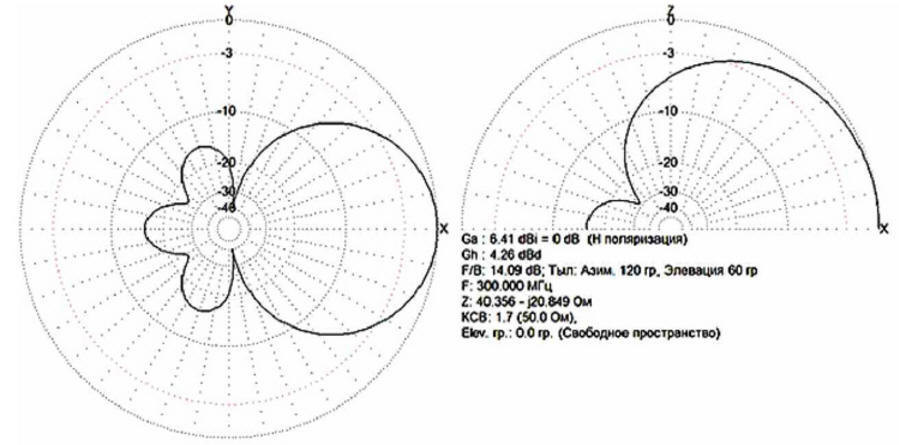
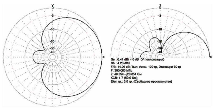
Compared to shortened dipole antennas, the ROV has smaller dimensions along the longitudinal axis and an increased gain. The design provides work on the radiation of all conductors of the antenna device. The first loop vibrator from the side of the direction of reception and transmission of the ROV is made in the form of an isosceles triangle with feed points at the top, with a base 0,4λ longslave and with sides 0,3λslave each. The second loop vibrator is made in the form of a Pistohlkors loop-vibrator with a length of linear conductors commensurate with λslave. Loop vibrators are placed in the same plane, and the connection to the power node of the conductors of the sides of the triangular vibrator is made with their crossing, i.e., out of phase. A coaxial power cable with a rigid structure, for example, in a tubular version of the conductors, is laid with an input through the zero potential point, i.e., the middle of the linear uncut conductor of the Pistohlkors loop vibrator. In the power node, the cable braid is connected in a section to the end of one conductor, and the central core to the end of the other. The antenna works as follows. When a high-frequency generator (see Fig. 1) is connected to the power points "a" and "b" of the power unit 7, currents flow inversely proportional to circuit resistance. In conductor 2, an increased current will flow relative to conductors 3 and 1 due to the lower input resistance of the frame vibrator 5 than the loop vibrator 6, but the radiation of the latter will be increased due to two closely spaced conductors 4 and 2. At the same time, due to the fact that in loop-vibrator 5, conductors 6 and 1 are located in close proximity to each other, and in an isosceles triangle 4, conductor 5 is connected between the conductors of the side crossed sides 6, then the currents in conductors 4 and 5 will be in phase with a phase difference relative to conductor 6. This ensures with cross switching, phase approximation to currents, similar to currents in a reflector and an active vibrator or in an active vibrator and the first director of Uda-Yagi antennas, but completely due to conduction currents, in contrast to induced, i.e., weaker currents in passive antenna vibrators Uda Yagi. Taking into account the fact that the conductors of the loop-vibrator 1 and 2 are separated in space by a distance commensurate with 3λslave, from the conductor 2 to the height of an isosceles triangle and are parallel, then the formed spatial system of radiating conductors of the antenna array creates a directed radiation of the electromagnetic field along the axis 8, perpendicular to the location of these conductors. In addition to this, currents in conductors 3, located symmetrically, but at an angle to this axis, also radiate an electromagnetic field into space, but with mutual compensation of opposite longitudinal components and unilaterally directed transverse components integrating into the total radiated electromagnetic field. Thus, in contrast to radiating systems with connecting lines, in the proposed technical solution, all conductors 2, 3, 5 and 6 participate in the radiation of an electromagnetic field, providing a total increase in the directional coefficient of the system and the efficiency of its operation. The operation of the proposed antenna was simulated in the MMANA program (Fig. 2 and Fig. 3) at a frequency of 300 MHz (wavelength - 1 meter) for simplicity and clarity during modeling and subsequent size normalization. Injection molding machine with a length commensurate with 0,2λslave, has a sectoral directivity with a different width of the radiation pattern in the plane of the conductors of the vibrators and in the plane perpendicular to it, with an increased gain. The ratio of forward to backward radiation characterizes the improved spatial selectivity corresponding to six-element Uda-Yaga antennas with twice the length of the traverse. The zero potential points of both vibrators can be connected to a grounded metal carrier bar providing ESD protection and lightning protection.
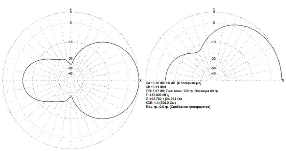
For the use of antennas on the amateur radio bands of 144 and 432 MHz, a visual comparison of the configurations and the ratio of the sizes of the shortened two-element antenna considered by the authors of the book [1] (Fig. 4) with the versions of the proposed ROV (Fig. 5) and the ROV with an internally installed director (Fig. 6). The numerical values of the parameters of these antennas are summarized in the table, and graphically, most clearly, the electrical characteristics are displayed in the form of radiation patterns (respectively, Fig. 7-9).
The practical implementation of the design in the form of an independent antenna is similar to the repeatedly described two-element antenna "wave channel", only with a loop-vibrator deployed into the plane of the vibrators. devices. Table
The manufacture of the antenna version with the director is also carried out similarly to that described. An additional conductor is placed between the loop and linear vibrators with strict observance of its cross section, installation location and length. In cases where other materials are used, a preliminary check of the antenna capabilities must be simulated in the MMANA program. The files for the MMANA program for the antennas shown in the table can be downloaded from ftp://ftp.radio.ru/pub/2015/07/maa.zip. Literature
Authors: V. Milkin, N. Kalitenkov, V. Lebedev, A. Shulzhenko
A New Way to Control and Manipulate Optical Signals
05.05.2024 Primium Seneca keyboard
05.05.2024 The world's tallest astronomical observatory opened
04.05.2024
▪ Triple camera in smartphones - the trend of the mobile industry ▪ How to beat smartphone addiction ▪ Any material turns into glass
▪ section of the site House, household plots, hobbies. Article selection ▪ article by Ursula Le Guin. Famous aphorisms ▪ article What man-made objects on Earth are visible from space? Detailed answer ▪ article Maintenance of steam boilers for gaseous fuels. Standard instruction on labor protection ▪ article self-igniting candles. Focus Secret
Home page | Library | Articles | Website map | Site Reviews
www.diagram.com.ua | |||||||||||||||||||||||||||||||||||||||||||||||||||||||||||||||||||||||||||||||||||||||||||||||||||


 Leave your comment on this article: