|
|


 Arabic
 Bengali
 Chinese
 English
 French
 German
 Hebrew
 Hindi
Hindi Italian
 Japanese
 Korean
 Malay
Malay Polish
 Portuguese
 Spanish
 Turkish
 Ukrainian
 Vietnamese
|
ENCYCLOPEDIA OF RADIO ELECTRONICS AND ELECTRICAL ENGINEERING Marching tri-band delta. Encyclopedia of radio electronics and electrical engineering
Encyclopedia of radio electronics and electrical engineering / HF antennas Recently, shortwavers often go on various expeditions around their native land and take an amateur radio station with them. Moreover, in the intended places of work, there are not always trees for installing simple wire antennas, and carrying antenna masts with you is a noticeable additional weight load. Murmansk radio amateurs have developed a simple antenna, which is installed using a fishing rod. This tri-band Delta was designed for field use. It also differs from the previous single-band version described in [1] by a larger suspension height and installation method. The antenna itself (Fig. 1) is range triangles inscribed in each other, powered by a coaxial cable with a wave impedance of 50 ohms, connected to one of the legs. The triangle of the 20-meter range antenna has a perimeter of 21,6 m, and its feed point is 5,31 m away from its top. The perimeter of the 15-meter antenna triangle is 14,4 m, and the feed point is 3,54 m the distance is 10 m. The triangle of the 10,7-meter range antenna has a perimeter of 2,63 m, and the feed point is 1 m away from its top. The distances between the triangles when mounting the antenna are shown in fig. XNUMX.
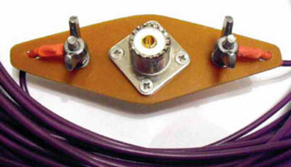
Antenna sheets are made of single-core mounting wire with a cross section of 0,5 mm2 in PVC insulation. The ends of the webs are attached to fiberglass plates (Fig. 4) with PL-2 connectors installed on them for connecting coaxial power cables using soldered tips and M239 bolts. The corners of the canvases are interconnected with fishing nylon cord brand "Danline" with a diameter of 3 mm, resistant to stretching and ultraviolet. To keep the shape of the antenna unchanged, after fitting on the ground, "dead" knots are tied in the corners of the attachment.
The mast of the antenna is a 9 m fiberglass fishing rod. A textolite ring is fixed at the top of the mast, to which, in turn, with the help of winding rings from a fishing store, a block for a cable and carabiners for two quickdraws are attached. A nylon cord, which connects the vertices of all triangles, is passed through the block, and its lower end is attached to a tripod. The lower corners of the triangles are also stretched with a cord and fixed to the branches of bushes or pegs for a tourist tent. After climbing the mast and stretching the antenna web, all three antennas are tuned to resonance. The length of the triangles of the antennas must initially be taken somewhat larger than given at the beginning of the article, since cutting off the excess is easier than soldering the missing one. SWR antennas - no more than two or three, depending on the range. During the tuning process, it also turned out that the resonant frequencies of the antennas depend on the underlying surface. On the shores of the salty sea, he tends to go down, and on a granite hill - up. For example, for a range of 20 meters, the change in the resonance frequency was more than ± 250 kHz (13860 ... 14380 kHz) at a calculated frequency of 14120 kHz! The antenna tuner built into the transceiver, of course, easily coped with this. The main problem in the development of this antenna was the triangle switching system. A switch (for example, manual mechanical) for three positions can also be located in the shack, but then three cables must be pulled to the antenna. And this is extra weight on the expedition! In addition, for loop antennas, it is required to switch not only the central conductors, but also the braids. Running out of the tent and switching connectors on a single cable is also not an option, and a waste of time. I did not come across suitable industrial switches, and I saw only one way out - to design and manufacture the switch myself for my specific task! I immediately decided on the requirements for it: push-button, quasi-sensor with blocking and mutual switching off. For the switch control panel, I liked the case from the old dial-up modem. Its LEDs have changed their purpose - they now indicate not only the switching on of the switch, but also the antenna connected at the moment. The switch was based on a three-state trigger circuit on a DD1 microcircuit, described in [2], supplemented with VT1-VT3 transistor switches and a supply voltage regulator on a DA1 microcircuit (Fig. 3).
The relay switching unit for antennas (Fig. 4) is made in a separate case, which is soldered from fiberglass laminated on both sides and pasted over with a decorative film (Fig. 5). The control cable is a twisted pair 4x2 for UTP-5e computer networks, about 15 m long. To prevent interference and false positives, a ferrite tube from the signal cable of a computer monitor is put on one of the ends of the cable. The relay coils are shunted with capacitors for the same purpose. Relay K1 - K6 - 882N-1CP-S (Chinese company SONG CHUAN) for an operating voltage of 5 V with one group of normally open contacts. The whole design is designed to be powered by a car battery or transceiver power supply.
In contrast to the previous design [1], where the base of the antenna mast was fixed by driving a car wheel onto the mounting platform, here a tripod was used, which eliminated the “auto-dependence” of the antenna. The tripod is made of a 150 cm long sanitary PVC pipe with an inner diameter of 50 mm and a cork in the socket, a double-socket coupling, and old duralumin ski poles. Three holes are drilled in the coupling socket for 120о and installed furniture hinges. The hinge screws protruding from the inside are filed off. Ski poles on the side of the handles are sawn off to the required length, then the same side is put on the hinge hinge and minted with a core. To fix the coupling in the deployed position of the tripod, coaxial through holes with a diameter of 5 mm are drilled in it and the pipe, into which a "weaving" nail is inserted. A halyard is attached to the same nail, with which the entire structure of triangles rises. Guys made of propylene cord are wound on a reel made of a piece of PVC cable channel with a section of 15x25 mm. The entire nylon cord-branch is placed in it and does not get confused. Each tripod leg is reinforced with an additional guide. The design of the tripod is shown in the photograph (Fig. 6).
The procedure for installing the antenna is as follows. First, the tripod is moved apart, then the mast, after putting on it a textolite ring with clockwork rings, to which carabiners with nylon cords of guy lines and a block are attached. Pass the halyard through the block and raise the antenna. Colleagues hold braces. Having raised the triangles, they straighten them, the assistant pulls one corner, moving away from the mast, I simultaneously tighten the other, we fasten or deepen the pegs. We connect the cables, loosening and pulling the guys, we align the mast vertically so that it does not bend much to the side. Full deployment time takes no more than half an hour. With this antenna, several trips were made to the battlefields of the Great Patriotic War on the Kola Peninsula, the islands of the Barents and White Seas. Literature
Author: Dmitry Inozemtsev (UA1ZKI)
Machine for thinning flowers in gardens
02.05.2024 Advanced Infrared Microscope
02.05.2024 Air trap for insects
01.05.2024
▪ Ford smart suspension with pothole protection ▪ LG's first wall-mounted projector ▪ Single-chip system Ambarella S3L
▪ section of the site Winged words, phraseological units. Selection of articles ▪ article Sukhomlinsky Vasily Aleksandrovich. Famous aphorisms ▪ article How do tornadoes start? Detailed answer ▪ article Blood-red hawthorn. Legends, cultivation, methods of application ▪ article Antenna switch. Encyclopedia of radio electronics and electrical engineering
Home page | Library | Articles | Website map | Site Reviews
www.diagram.com.ua |


 Leave your comment on this article: