|
|


 Arabic
 Bengali
 Chinese
 English
 French
 German
 Hebrew
 Hindi
Hindi Italian
 Japanese
 Korean
 Malay
Malay Polish
 Portuguese
 Spanish
 Turkish
 Ukrainian
 Vietnamese
|
ENCYCLOPEDIA OF RADIO ELECTRONICS AND ELECTRICAL ENGINEERING Refinement of the Baofeng UV-5R antenna. Encyclopedia of radio electronics and electrical engineering
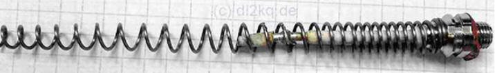
Encyclopedia of radio electronics and electrical engineering / VHF antennas For the Baofeng UV-5R transceiver, its standard antenna needs to be improved: it is not tuned accurately, and the losses on the 144 MHz band are high. It is easy to modify so that it works properly on both bands of this transceiver. Refinement begins with disassembly of the antenna. To do this, it must be disconnected from the transceiver and held for 10 ... 15 minutes in hot water (a boiled kettle will do). Then, holding the antenna by the connector and gently shaking (but not rotating around the axis), remove the plastic cover. The antenna itself is glued with something like silicone inside to the case in its upper part, so if you can’t remove it, you need to shake the case in the upper part harder. When the case is removed, you will be left with a yellowish-coated steel spring wound around the connector body, with a small capacitor inside. According to the electrical circuit, this is shortened by folding into a λ / 4 GP coil at 144 MHz (matching is a tap from this coil) and extended to about 0,35λ GP at 432 MHz, matched by a series-connected capacitor. It becomes clear why the lower part of the antenna heats up when transmitting at 144 MHz. After all, this is, in fact, a coil of a matching device (SU), matching the low (several ohms) radiation resistance of a short GP. And making a coil of such a SU from galvanized steel wire is a bad idea. The quality factor will turn out to be low (the conductivity of zinc is almost four times worse than copper), and the coil will heat up. This is what is observed in practice: when transmitting in the 144 MHz band, the lower part of the antenna heats up to 45 ... 55 in a few minutes оC. And this is precisely the heating of the antenna due to thermal losses in it, and not heat transfer from the transceiver chassis. To verify this, just unscrew the antenna - it is significantly hotter than the chassis. Another weak point of the stock antenna is the capacitor. First, it is very small ceramic, which introduces losses and limits the power capacity. Secondly, its thin wire leads are soldered on one side to the connector, on the other - to the antenna helix. And this can lead to mechanical destruction of this capacitor after several twisting and unscrewing of the antenna. After all, the bottom of the steel spring of the antenna is not soldered, but simply “screwed” onto the connector body, that is, it can rotate slightly about the vertical axis along with the capacitor lead soldered to it. This is exactly what happens if, when screwing in and out, hold the antenna not by the bottom, but by the middle. And the other terminal of the capacitor is soldered into the connector, and the rigidity of the design of the capacitor and its terminals is not enough for the connector tube to turn after the antenna spring. The capacitor leads are twisted, it is mechanically damaged. Descriptions of cases of failure of this capacitor are not uncommon. This capacitor must be replaced with a more reliable one - electrically and mechanically. The easiest way is to make a constructive capacitor from a coaxial cable. This will require a length of 42...45 mm semi-rigid cable with PTFE insulation (for example, HF086). Having removed the braid tube by about 2 ... 4 mm, they expose the central core and solder it into the connector. A heat-shrinkable tube 35 mm long is put on the cable and the shank of the connector. Heat it so that the last 1 cm of the braid remains uncovered by the tube. Stepping back about 30 mm from the connector, a piece of bare tinned wire with a diameter of 0,5 ... 0,8 mm and a length of 10 ... 12 mm is soldered to the braid, wrapping it in a ring around the braid. Approximately 5 mm of this lead is left freely protruding perpendicular to the surface of the coaxial cable. Above the soldered ring, another piece of heat-shrinkable tube 10 mm long is put on the cable and fired. The result was a 4 pF capacitor with PTFE insulation (low losses) and mechanically strong. Even if the antenna spring then rotates relative to the connector, the central core soldered to it from a solid and relatively thick wire will simply rotate in the fluoroplastic cable insulation without negative consequences. Now let's deal with the losses in the coil. Having degreased the antenna spiral and removed the remnants of silicone from its top, we will silver the steel spring. The old method of immersion in a spent fixer is now unlikely to work: there are no photographic films and fixers for them. But silver salts for silvering in an aqueous solution can be found. For this, one test tube of the solution is enough: first, the lower part of the antenna is silvered, then it is turned over and the upper part is lowered into the solution. After silvering, rub the spiral with a flannel cloth to a shine. At the same time, you need to take care of your hands: black flakes of excess silver, removed with a cloth, are then poorly washed off the skin. "For beauty" you can also cover the spiral with a thin layer of colorless nitrolac. Probably, instead of silvering, you can simply tin the spiral with good solder, but the author did not try this. Now put the spiral on the connector and tightly wind it. Then, with tweezers, the protruding free wire lead is pulled out and soldered (when setting the connection point, you may have to change it) to the 16th turn of the spiral, counting from the bottom (Fig. 1).
To set it up, you will need to press and stretch the spiral (for sure), change the connection point of our capacitor from the cable segment to the spiral (maximum plus or minus 1 turn, but this may not be required), the capacitance of this capacitor, i.e. the length of the cable (most likely , it will not come to that). The minimum SWR should be adjusted approximately 1 MHz higher than the desired frequency on the 144 MHz band and 3 ... 5 MHz higher on the 432 MHz band. Then, when you put on a cover, due to the influence of plastic, the frequencies will decrease accordingly. On fig. 2 and fig. Figure 3 shows the dependences of the SWR on the frequency for the modified antenna.
After completion, the 144 MHz antenna heats up significantly less, and repeaters began to open from those problem areas (for example, inside a reinforced concrete house), from which they could not open with the original antenna. Author: Igor Goncharenko (DL2KQ)
A New Way to Control and Manipulate Optical Signals
05.05.2024 Primium Seneca keyboard
05.05.2024 The world's tallest astronomical observatory opened
04.05.2024
▪ Face mask with microphone and speakers ▪ There is water on the asteroid Cybele ▪ Power supply Ecosol Powerstick
▪ section of the site Grounding and grounding. Selection of articles ▪ article by Franz Kafka. Famous aphorisms ▪ article Who Invented Champagne? Detailed answer ▪ article Backout tree. Legends, cultivation, methods of application ▪ article History of metal detectors. Encyclopedia of radio electronics and electrical engineering
Home page | Library | Articles | Website map | Site Reviews
www.diagram.com.ua |


 Leave your comment on this article: