|
|
ENCYCLOPEDIA OF RADIO ELECTRONICS AND ELECTRICAL ENGINEERING Small-sized antennas for portable stations of CB communications (Part 2). Encyclopedia of radio electronics and electrical engineering
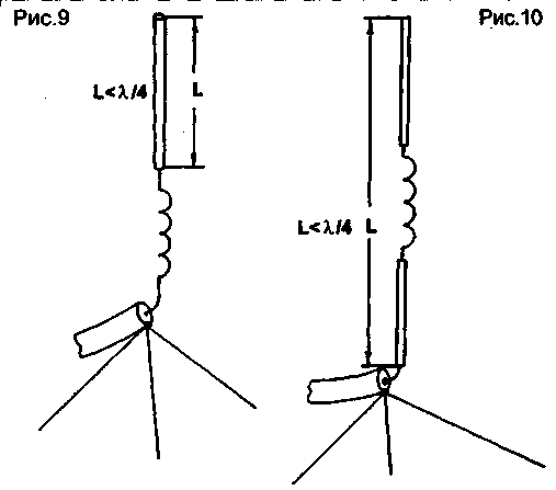
Encyclopedia of radio electronics and electrical engineering / HF antennas 5. RESONANT WHIP ANTENNAS EXTENDED BY INDUCTANCE In portable and mobile CB radios, antennas with a length of 30 ... 100 cm for portable and up to 1,5 meters for mobile radios are used. Having calculated the input resistance of the active parts of such short pins for a frequency of 27 MHz, we obtain values from 0,5 Ohm for 30 cm to 10 Ohm for 1,5 m. Of course, it is unreasonable to connect such short pins to the output stage of the transmitter without appropriate coordination. Firstly, the efficiency of such a pin as an antenna is low, and secondly, matching the low resistance of the pin with the output stage of the transmitter is very difficult. The most rational solution that came to solving this problem was that the pin is part of a complex system, which is a shortened antenna. Hereinafter, the efficiency of the pin in such a system is considered. The classic whip antenna is a quarter-wavelength vibrator and a grounding system underneath. In the simplest case, the grounding system is a system of quarter-wave balances. Naturally, it is difficult to use such a system for a portable station. Therefore, they try to shorten the antenna and counterweights. The simplest thing in this case is to include an extension coil in the antenna. But even here the question is, at what point of the antenna to include an extension coil for maximum effect. The body of the station plays the role of the counterweight system. You should immediately pay attention to the most inefficient way to lengthen a short antenna - the inclusion of an extension coil in its base (Fig. 9). The maximum current flowing through the antenna is at its base. From the theory of antennas, it is known that in order to obtain the maximum radiation of the antenna and, consequently, its maximum efficiency, it is necessary to ensure the maximum current in the radiating element of the antenna and the maximum voltage at its radiating end. Here, the maximum current flows through the coil, so the maximum interaction with the medium occurs through the coil.
The advantage of an antenna with an extension coil at the base is that, due to the large capacitance of the pin, such antennas have a relatively large bandwidth, allowing them to operate in the entire MW or amateur bands. Another type of antenna is an antenna extended with a coil in its middle (Fig. 10). Here, a significant current strength is already achieved at the base of the antenna, the upper part of the pin plays the role of a capacitive load. Due to the increase in the terminal capacitance, the antenna bandwidth increases to a value that allows it to operate in the entire MW range, and its efficiency also increases significantly. The pin to the coil is the main radiating element, it should be made as thick as possible, especially since it also holds the extension coil. The pin after the coil is already a capacitive load. It can be made thinner. Placing even a small capacitive load at the end of such an antenna increases the efficiency of its operation, but reduces the mechanical strength. You should also pay attention to the fact that, in principle, with the bad "ground" that occurs in portable radio stations, all types of short antennas work equally badly, and there is no significant difference in their use. But already connecting a quarter-wave counterweight shows a difference in the efficiency of different types of antennas. The effect is also observed in mobile car radios, where the car body is an effective ground. The resistance of an ideal quarter-wave vertical antenna - a spike over an ideal conducting surface - is 36 ohms. The resistance of an ideal shortened MW antenna, depending on the degree of its shortening, is 10 ... 20 Ohm. Given that the real "ground" of such antennas is far from ideal, in the general case, such antennas can be matched with both the coaxial power cable of the antenna in a mobile car station (usually a 50-ohm cable is used here), and with the output stage of a portable radio station, a bad "ground " which increases the resistance of a short antenna to 50 ... 100 Ohms. 6. PRACTICAL DESIGNS OF WHIP ANTENNAS EXTENDED BY INDUCTANCE Basically, all shortened antennas of portable radio stations have the form shown in Fig. 11. A coil with an inductance of about 2 μH and a pin with a length of about 120 cm constitute an antenna system operating in the 27 MHz band. And only the efficiency of the antenna and its bandwidth depend on the different design of the coil and the pin. The antenna shown in Fig. 7 is also shown in many other, earlier sources [7, 8,9, 10, XNUMX].
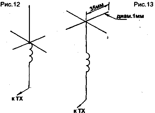
When testing the antennas from [7, 8], an identical 2 μH extension coil was used for them and the following results were obtained. Input impedance with a quarter-wave counterbalance - 35 Ohm, with a radio station housing - 80 Ohm. Bandwidth at half power (-3 dB) - 600 kHz with a counterbalance, 750 kHz with a radio station body. The human influence exerted on this antenna is small and its reactivity is low. The frequency shift when a quarter-wave counterbalance was connected reached 700 kHz. When testing the antenna from [9], where the length of the pin was 80 cm, the extension coil was 18 turns of PEL 0,55 wire wound on a frame with a diameter of 4 mm turn to turn, the following results were obtained. Input impedance with a quarter-wave counterbalance - 60 Ohm, with a radio station counterweight-case -1100m. The bandwidth with a quarter-wave counterbalance is 800 kHz, with the station body - 900 kHz. The offset of the resonant frequency when the counterweight is connected is almost 1 MHz. When testing the antenna from [10] with a pin length of 0,8 ... 1,2 m, the extension coil was 25 turns of PEL 0,35 wire wound on a frame with a diameter of 5 mm turn to turn, results similar to the antenna from [ 9]. Of particular interest are short antennas - up to 50 cm long. Moreover, these antennas are not so significantly inferior in the communication range to long antennas - about 1 m long. The antenna from [11] is a pin 45 cm long with an extension coil containing 60 turns of PEL 0,5 wire on a frame with a diameter of 5 mm, wound round to round. When testing such an antenna, the following results were obtained. With a quarter-wave counterbalance, the input impedance is 75 ohms, the bandwidth is 700 kHz. With the body of the station as a counterbalance, the input impedance is 120 ohms, the bandwidth is 900 kHz. The resonant frequency shift when a quarter-wave balance was connected was 1,2 MHz. Human influence on the antenna is higher than in long antennas. The increase in the input impedance and the expansion of the bandwidth of a short antenna (45 cm) compared to a long one (1 m) indicates that the extension coil of a short antenna is of low quality. But an increase in the quality factor of the extension coil has little effect on the efficiency of such short antennas. Connecting a counterweight shifts the resonant frequency of the antenna up. For efficient operation of the radio station when connecting a counterweight, in this case, it is necessary to provide for the on-line adjustment of the inductance of the extension coil. It is desirable in transceivers when switching the antenna pin to use different extension inductances for the receiver and transmitter. This allows you to optimally match the pin for both reception and transmission. Naturally, if the resistance of the input of the receiver and the output of the transmitter differ insignificantly, one extension coil can be dispensed with, since in this case the shift in the resonant frequency of the system when switching RX / TX is small. But here it is already necessary to decide from practical conditions which is easier - to switch the extension coils or to bring the inputs of the transmitter and receiver to the same value. In "proprietary" equipment, they strive for the latter, although there are options with tuning the receiver input when switching the antenna. In home-made equipment in the 27 MHz band, the issue of antenna matching in the receive and transmit modes is often not given due attention, which leads to a decrease in the efficiency of portable radios. In [12], an antenna with a shoulder length of 110 mm and an extension coil in the center, having 130 turns of PEL 0,15 wire, wound round to round on a frame with a diameter of 6 mm, is described. When tested, this antenna showed the following results. With a quarter-wave counterbalance, the input impedance was 90 ohms, bandwidth . - 400 kHz, with a counterweight-case of the radio station, the input impedance was 140 ohms, the bandwidth was 600 kHz. The passband offset when connecting a quarter-wave counterweight was 900 kHz. The addition of a capacitive load, shown in Fig. 13, made it possible to reduce the frequency offset when connecting counterbalances to 600 kHz. The bandwidth increased by 50 kHz in both cases. The input impedance decreased - with a counterweight it became 75 ohms, with the station body - 90 ohms. The field strength increased 1,3 times. All this speaks to the advantages of capacitive loading for these types of antennas. It should be noted that the capacitive load shown in Fig. 12 works more efficiently, but unfortunately, it is more difficult to implement in practice than the load in Fig. 13.
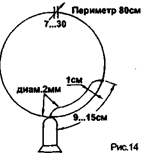
A comparison of the field strength values generated by an antenna with a central inductance and an extension inductance at the base showed that, in practice, an antenna with a central inductance, equal in height to an antenna with an inductance at the base, creates a field strength of about 1,4 ... 1,6 times big. By adding a capacitive load, the advantages of such an antenna are further enhanced. The measurements were carried out with quarter-wave balances. When using the radio body as a counterweight, the advantage of the antenna with a central inductance was weaker, the field strength was only 1,2 times greater than that generated by the antenna with an inductance at the base. This suggests that for portable stations there is not much difference in the type of whip antenna used, but for mobile stations it is better to use an antenna with a center load inductance. In any case, it is desirable to use a capacitive load, even in the form of a ball with a diameter of 5...20 mm. A capacitive load also has an effect when used with an antenna with an extending inductance at the base. In practice, for portable stations, antennas made of thick copper wire with a diameter of 2 ... 2,5 mm can be used. Antenna with a smaller diameter is less mechanically strong and has a lower efficiency. For the manufacture of antennas for mobile vehicle stations, you can use short "waders" or suitable antennas from army radio stations of the appropriate length and, most importantly, strength. 7. NON-RESONANT WHIP ANTENNAS Non-resonant whip antennas are the most inefficient of all short whip antennas available. They lose in field strength by 2...3 times to whip antennas of the same length with an extension inductance; these antennas are much more insensitive to human influence. But still they are still used, however, mainly in only two types of transmitters. The use of such non-resonant antennas is justified only in simple toys, the communication range with which is not higher than 50 ... 100 m. For more efficient communication, it is necessary to use only a resonant antenna, although decoupling stages for the simplest circuits must be placed in front of it. As experience shows, Western simple radio stations, which consume more power than the domestic Hummingbirds, but operate on non-resonant antennas, provide a much shorter communication range. The third case of using short non-resonant antennas is the incorrect construction of the transmitter output stage with its antenna matching circuits. As a result, when a normal resonant antenna is connected to it, whether full-sized or shortened, it self-excites. Although such transmitters often have a P-loop at the output, its operation is inefficient. 8. MAGNETIC LOOP ANTENNAS OF PORTABLE MW-Radio STATIONS I have not seen magnetic loop antennas in any of the portable CB radios. But this does not mean that their use in this type of radio stations is impractical. I made magnetic loop antennas for the 27 MHz band with the dimensions shown in Fig. 14.
The antenna showed the following results. Input impedance - 75 ohms, with very low reactance. Bandwidth - 600 kHz. The antenna was made of a two-millimeter insulated copper wire of the PEL type, the air tuning capacitor was mounted on a fiberglass base. The antenna turned out to be very insensitive to the influence of a person and counterweights. Since such an antenna mainly radiates the magnetic component of the electromagnetic wave, it cannot be strictly compared in terms of such an indicator as the level of field strength with a whip antenna, because the latter radiates mainly the electrical component of the electromagnetic wave, and measurements for the pin should be carried out according to the electrical component of the EMW, and the frames - according to the magnetic component of EMW. Two antennas, shown in Fig. 14, were connected to radio stations of the "Kolibri-M" type and the communication range was tested in comparison with the standard helical antenna. It turned out that, all other things being equal, the communication range when using magnetic antennas was at least 1,5 times longer in open areas, and 2 ... 3 times longer in urban conditions. In this case, the directivity of the magnetic antenna had a significant effect. Author: I. Grigorov (RK3ZK, UA3-113); Publication: N. Bolshakov, rf.atnn.ru
Machine for thinning flowers in gardens
02.05.2024 Advanced Infrared Microscope
02.05.2024 Air trap for insects
01.05.2024
▪ Century CCA-DPHD4K6 active adapter ▪ New refrigeration method for refrigerators
▪ site section Power supplies. Article selection ▪ article Management. Lecture notes ▪ How did the major religions originate? Detailed answer ▪ article Demercurization measures. Standard instruction on labor protection ▪ article Attachment to the VCR. Encyclopedia of radio electronics and electrical engineering
Home page | Library | Articles | Website map | Site Reviews www.diagram.com.ua |


 Arabic
 Bengali
 Chinese
 English
 French
 German
 Hebrew
 Hindi
Hindi Italian
 Japanese
 Korean
 Malay
Malay Polish
 Portuguese
 Spanish
 Turkish
 Ukrainian
 Vietnamese


 Leave your comment on this article: