|
|
ENCYCLOPEDIA OF RADIO ELECTRONICS AND ELECTRICAL ENGINEERING Another option for a vertical directional antenna. Encyclopedia of radio electronics and electrical engineering
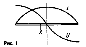
Encyclopedia of radio electronics and electrical engineering / VHF antennas In a previous article by the author (V. Polyakov. Vertical directional antenna. "KB magazine", No. 5, 1998, p. 27-31) A two-element directional antenna consisting of two active vertical vibrators was described in detail. In the process of experiments with it, another way of powering vertical vibrators was invented, without the use of a quarter-wave two-wire line. Maybe this is to some extent a return to the old and well-known, nevertheless, the antenna worked, was easily tuned, showed good results and was used in practice. We offer this construction for the judgment of readers. According to the ideology, this antenna is still a ZL-beam with two closely spaced vertical half-wave vibrators fed almost in antiphase (the phase shift of the currents in the vibrators is about 215°). The changes relate to the way the vibrators are powered. Let's turn to Fig. 1, which shows a continuous half-wave vibrator and the distribution of current I and voltage U in it.
The graphs of these distributions correspond almost exactly to segments of sinusoids. At point X, displaced at some distance from the middle of the vibrator, its resistance, in full accordance with Ohm's law, is determined by the ratio of voltage to current, R=U/I. It is equal to zero in the middle of the vibrator (since the voltage vanishes here) and increases proportionally to tg(2nX/L,) when the feed point is displaced by a distance X from the middle of the vibrator. In this way, by the way, the Windom antenna is powered by a single-wire feeder with a resistance of about 600 ohms. We will need a resistance of about 25 ohms, so the displacement of the power point from the middle of the vibrators will be very small. The electrical circuit of the proposed antenna with approximate dimensions given in wavelengths is shown in Fig.2.
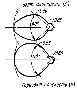
A power cable with a wave impedance of 50 ohms is connected to the YY points, providing their anti-phase excitation. These points are connected by short "thick" segments of conductors to the feed points of the X-X vibrators. "Thick" conductors are needed here to reduce their inductive resistance, which, however, will be compensated when tuning the antenna, and, as it turned out, does not have a significant effect. For the supply feeder, the input impedances of the vibrators are connected in series, which is why the input impedance of the vibrators at points X-X should be about 25 ohms. With equal success, the antenna can be matched with a 75-ohm cable, just the distance from the middle of the vibrators to the X-X points will be a little more. If the vibrators were the same, they would fire exactly out of phase and the antenna would radiate badly, with a radiation pattern of two identical lobes back and forth. For the necessary phasing, the front vibrator is made somewhat shorter than the half-wave, and the rear one is somewhat longer (as a reflector should be). The electrical lengths of the vibrators in Fig. 2 are given taking into account the "natural" shortening of the vibrators having a finite thickness. Shortening the front vibrator results in a phase shift of about 16° (0.045L) in the lead direction, while lengthening the rear vibrator results in the same phase shift in the lagging direction. The distance between the vibrators is 0,09L, so the wave radiated back by the front vibrator is exactly out of phase with the wave radiated back by the rear vibrator, and both waves are compensated. Therefore, there is no backward radiation. The phase difference between the waves radiated forward by both vibrators is more than 60°, and these waves are not compensated, forming a directional radiation. The described antenna was modeled in the 430 MHz range as follows: on a plate of foil-coated fiberglass with dimensions of 7x80 mm, the foil was cut in the middle and a cable (YY points) was soldered there, with a braid towards the reflector (it is more convenient to call the rear, longer vibrator). The vibrators were made of copper wire with a diameter of 1,8 mm and were attached to the glass-textolite strip with spring brackets (X-X points), so that the vibrators could be moved vertically. By such a movement, or by shifting the X-X points, it was possible to achieve SWR == 1 at the operating frequency. Suppression of back radiation was achieved by selecting the lengths of the vibrators. Here's what happened after tuning: the gain of the antenna compared to a single half-wave vibrator was 5 dB. Directional patterns in the vertical and horizontal planes are shown in Fig.3.
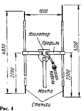
They are very typical for a two-element antenna and do not have any features. The opening angle of the diagram at half power is 110° in the horizontal plane (in azimuth) and 90° in the vertical plane (in elevation). In the latter case, the directional properties of the vibrators themselves come into play, adding to the directional properties of the emitter system. An estimate of the beam gain gives a value of 6,5 dB with respect to an isotropic radiator, which corresponds quite well to the above figure. Having received these results, it was decided to build a portable collapsible antenna for field operation on the 10 m band. Its sketch is shown in Fig. 4. The antenna was raised on a telescopic mast 6,5 m high, made of pieces of duralumin pipes with a diameter of 24 to 35 mm. In order for the mast not to be excited by the radiation field of the antenna, its length should not be a multiple of a quarter wavelength. Although this provision has not been experimentally verified, no noticeable effect of the mast of the indicated height on the operation of the antenna has been noted. Dielectric masts of any height can also be used. The mast was fixed in a vertical position with stretch marks from a polyamide fishing cord. At the upper end of the mast, a plate of thick (15 mm) organic glass (insulator) was fixed, to which the horizontal parts of the supply line were bolted. They were made of a duralumin U-shaped profile with a section of 35x20 mm. The dimensions of the profile are not critical, as long as it provides sufficient mechanical rigidity for mounting the vibrators. Petals were placed under the bolts of the profile to the insulator, to which the cable was soldered. To reduce the flow of currents on the cable sheath, two ferrite rings were put on it. The cable had no electrical contact with the mast.
The vibrators were made of two duralumin tubes 14 mm in diameter and 3000 mm long. At both ends, the vibrators were attached with topmasts from a thinner and very light tube. The topmasts could be moved and fixed with screws by adjusting the length of the vibrators. To the ends of the profiles (at points Х-Х), the vibrators were fastened with crimps made of soft duralumin and screws with threaded holes in the profile. While the screws are not clamped, the vibrators could be moved vertically with some effort, holding the lower topmast. The tuning of the antenna was reduced to the selection of the lengths of the vibrators by extending and retracting the lower topmasts. In this case, the directivity diagram was controlled. In practice, this is convenient to do when receiving a radio station, the signal from which is stable and comes in a ground wave. Rotating the mast, observe the radiation pattern. The author, experimenting on a garden plot 60 km from Moscow, received the radio station of the Moscow "Rescue Service" in the MW range of 27 MHz, and received a difference in reception "front" and "rear" of 4 ... 5 points (up to 30 dB). The vibrators were then shortened by 4% to tune to 28 MHz. Having received an acceptable diagram, move the vibrators vertically until a good SWR is obtained in the supply feeder. In this case, the vibrators are a little upset, but nevertheless it is better to repeat the operations for forming the diagram and matching several times in succession. This can be done in the working position of the antenna, maybe by lowering the mast to one knee, since it is only necessary to reach the lower topmasts of both vibrators for adjustment. In no case should you touch the topmast when the transmitter is on, since there are antinodes (maxima) of voltage at the ends of the vibrators and you can get high-frequency burns. In addition, the antenna is upset even when hands are brought to the ends of the vibrators. After adjustment, the antenna is lowered, all fixing screws are tightened and raised again to the working position. The dimensions shown in Fig. 4 were obtained after the antenna was tuned. To check the repeatability of the results, another time the antenna was assembled on the ground according to the given dimensions and raised without tuning. The radiation ratio forward / backward turned out to be about 25 dB, and the SWR was less than 2. Only a slight adjustment of the SWR was required by moving the vibrators vertically in their mounts. With this antenna, an experiment was carried out to receive signals from Scandinavian lighthouses on one of the days when there was no transmission on the 10-meter band. Having tuned the receiver to 28,268 MHz and directed the antenna to the northwest, the author patiently listened to the purest noise of the ether for an hour and a half. It must be said that the experiment took place in a fairly "quiet" place, where the air noise, reduced to the 50-ohm receiver input, was 0,08 ... 0,1 μV in the 2,4 kHz SSB band. Patience was rewarded with three, one strong and two weaker "bursts" of the signal from the Finnish OH9TEN lighthouse emitting a 20 watt vertical omnidirectional antenna. The "flashes" lasted from one to four seconds, and there is no doubt that these were signal reflections from sporadic meteor trails. Subsequent calculations gave values of attenuation of the meteor signal on this path of the order of 170...180 dB, i.e. a value that can be completely covered using a radiated power of several tens of watts, sensitive receivers and the simplest directional antennas like the one described. Thus, meteor communication on the "top ten" is quite possible! Author: Vladimir Polyakov (RA3AAE), Moscow; Publication: N. Bolshakov, rf.atnn.ru
A New Way to Control and Manipulate Optical Signals
05.05.2024 Primium Seneca keyboard
05.05.2024 The world's tallest astronomical observatory opened
04.05.2024
▪ Global satellite map of the rainforest ▪ Fluorescent glow to search for extraterrestrial life ▪ Under the gaze of the machine
▪ section of the site Tips for radio amateurs. Selection of articles ▪ article Self-loading wheelbarrow. Drawing, description ▪ article How many moons does Jupiter have? Detailed answer ▪ Article Spinach garden. Legends, cultivation, methods of application ▪ article The first electric battery. physical experiment
Home page | Library | Articles | Website map | Site Reviews www.diagram.com.ua |


 Arabic
 Bengali
 Chinese
 English
 French
 German
 Hebrew
 Hindi
Hindi Italian
 Japanese
 Korean
 Malay
Malay Polish
 Portuguese
 Spanish
 Turkish
 Ukrainian
 Vietnamese


 Leave your comment on this article: