|
|


 Arabic
 Bengali
 Chinese
 English
 French
 German
 Hebrew
 Hindi
Hindi Italian
 Japanese
 Korean
 Malay
Malay Polish
 Portuguese
 Spanish
 Turkish
 Ukrainian
 Vietnamese
|
ENCYCLOPEDIA OF RADIO ELECTRONICS AND ELECTRICAL ENGINEERING Rothammel antenna upgrade. Encyclopedia of radio electronics and electrical engineering
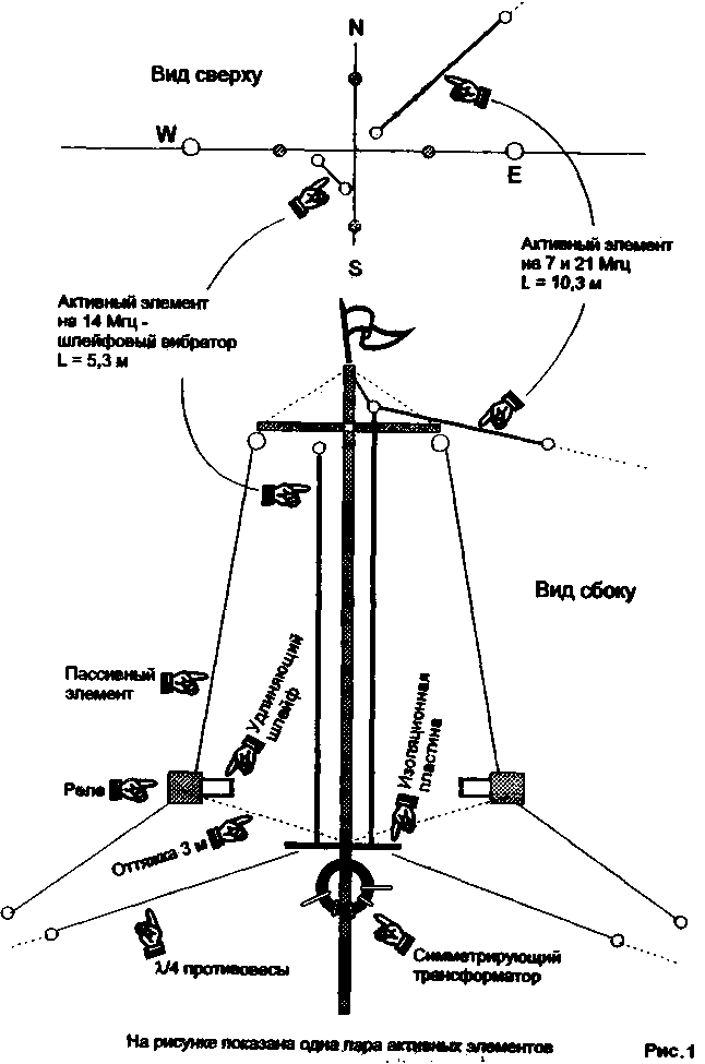
Encyclopedia of radio electronics and electrical engineering / HF antennas The design of a vertical antenna from the book by K. Rothammel was taken as a basis, but instead of a vertical half-wave vibrator, in order to increase the wave resistance, a stub emitter with a system of counterweights located at an angle of 120 degrees is used. The four passive antenna elements are bent at the same angle. Relays are installed in the middle of each passive element, Fig.1.
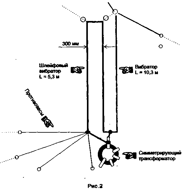
It is known that the maximum radiation of the antenna falls on the place where there is a maximum current. If the installation height (suspension) of the antenna is less than 1/4 lambda, then it is better to use the vertical location of the radiator (vertical polarization). Designing this antenna, proceeded from the following premise. Living in a panel 5-storey house, the roof of which is publicly accessible by definition, somehow I didn’t want to use quite expensive materials and nodes - very risky - will be hardened. Therefore, there was a desire to minimize the cost of its manufacture. The proposed antenna for the 20-meter range does not contain scarce materials and occupies an area of 10 by 10 meters, it works, in my opinion, not worse than a double square, and the radiation pattern switching time takes only one second. The basis of the structure is a metal (steel) pipe with a diameter of 25 mm and a height of 9 meters with a metal cross at the top. The length of each crossbar is 2,6 meters (1,3 m in each direction). Below, at a distance of 5,5 m, an insulating plate is installed, on which counterweights and a loop vibrator are mounted, stretched parallel to the pipe-mast. The distance between the active and passive elements at the top and bottom is not critical and is chosen 1 ... 1,5 m. The distance from the power point to the relay is 3 m and is determined by the length of the brace between the relay and the insulating plate. The cross is welded 0,5 m below the upper end of the pipe and braced with steel wire. The lower ends of the passive elements and counterweights are fixed on the roof through short braces and, as it were, reinforce the antenna, so one tier of braces coming from 1/3 of the pipe from above is quite enough. The length of the loop vibrator is about 5,3 m, and the distance between its wires is 30 cm. The length of the counterweights is 5,3 m, Fig.2.
The length of the passive element as a director is Yum, the relay contacts close the extension cable. The length of the passive element as a reflector is 11m, the relay contacts are open. A wire loop 1 m long is suspended on a guy line coming from the relay. Switching relays type RES-9, both groups of contacts are connected in parallel. Parallel to the relay windings, 0,01 μF capacitors are installed, Fig. 3. The radiation of the antenna (directional pattern) is switched by two toggle switches with a neutral position. One switches the direction east-west, the other north-south. Each position of the toggle switch connects the corresponding relay. 8 (eight) working combinations are possible: 4 positions - one director with three reflectors and 4 positions - two directors with reflectors, which corresponds to the choice of the following directions: North, North-East, East, South-East, South, South-West, West , Northwest. The antenna is powered by a 50 ohm coaxial cable. To balance and reduce noise when receiving with the same cable, 600 ... 2000 turns are wound on a ferrite ring with magnetic permeability (5 - 10 NN). The ring is located in close proximity to the feed point of the antenna.
Antenna tuning is reduced to selecting the length of the vibrator according to the minimum SWR, and by selecting the length of the reflector, it is necessary to achieve maximum back suppression. It is very convenient to do this, since the end of the reflector is low above the roof. According to correspondents, when compared with a dipole, the gain is up to two points, and the suppression of the back lobe reaches four. Without much deterioration in the parameters of the antenna, it can be made into three ranges, which is implemented in the final version. A 10,3 m long wire is placed parallel to the pipe-mast (not shown in the figure) from the feed point to the top of the pipe, and then a 14 m long wire (at a frequency of 7 MHz it has a high input impedance and does not affect the operation of the main antenna). Counterbalances of the same length are connected and the antenna starts working in the 21 MHz band, like a shortened GP, as well as in the 28 MHz band at the third harmonic. The number of counterweights on each of the ranges should not be less than four. It is also noted that the antenna works quite satisfactorily even on the XNUMX MHz band. At the fundamental frequency, the antenna has small radiation angles in the vertical plane and is very effective for long-distance communications. At short distances (distances), sometimes it loses to "rope" antennas. Author: V.Tsitko, RW4CB, Rtishchevo; Publication: N. Bolshakov, rf.atnn.ru
Machine for thinning flowers in gardens
02.05.2024 Advanced Infrared Microscope
02.05.2024 Air trap for insects
01.05.2024
▪ Ultrasound helps drugs reach their target ▪ Powerful PWM amplifier MSA240 ▪ Created an artificial pancreas
▪ section of the site For a beginner radio amateur. Article selection ▪ article Tearing off all and all kinds of masks. Popular expression ▪ article In which country is the oak that has its postal address located? Detailed answer ▪ article Determination of distances by the shadow of an object. Travel Tips ▪ article Fisherman's echo sounder. Encyclopedia of radio electronics and electrical engineering ▪ article The Mystery of the Dark Stripes. physical experiment
Home page | Library | Articles | Website map | Site Reviews
www.diagram.com.ua |


 Leave your comment on this article: