
|
|
ENCYCLOPEDIA OF RADIO ELECTRONICS AND ELECTRICAL ENGINEERING Six-band whip antenna. Encyclopedia of radio electronics and electrical engineering
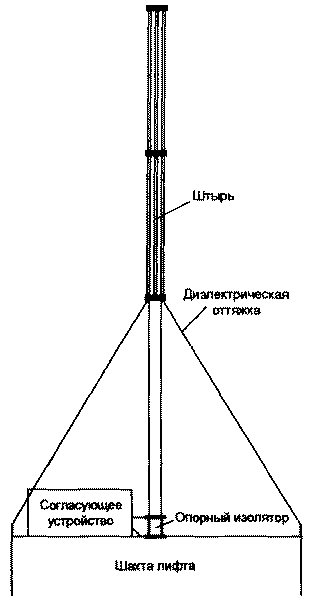
Encyclopedia of radio electronics and electrical engineering / HF antennas The difference between this antenna and similar multi-band GPs, which are tuned to the operating frequency by a matching unit located at the base of the vertical radiator, is the absence of switching elements or elements with variable parameters (capacitors, inductors) in this unit. Such a solution reduces the likelihood of failure of the matching unit due to adverse weather conditions, and increases the reliability of the antenna as a whole. This article discusses an antenna that can be placed on the roof of an elevator shaft in a multi-storey building. It is intended for use on amateur radio stations that have a matching unit, separate or built into the transceiver, that allows you to work without power reduction to the load with an SWR of no more than 3. This antenna has a non-tunable matching device that provides the specified level of matching in most of the six amateur bands (7 -21 and 28 MHz). The matching device is installed at the base of the antenna. The antenna itself (Fig. 1) is a vertical radiator - a pin 6,25 m high. Up to 1/114 of its height, it is made of a steel pipe with an outer diameter of 2 mm, and the upper 3/40 of the pin, in order to reduce its weight and antenna windage, are made of four parallel steel pipes with a diameter of 007 mm (with an equivalent radius the same as that of bottom tube). The emitter is mounted on a support insulator. In a practical design, a steatite insulator model SB-XNUMXS was used.
The difference between this antenna and similar multi-band GPs, which are tuned to the operating frequency by a matching unit located at the base of the vertical radiator, is the absence of switching elements or elements with variable parameters (capacitors, inductors) in this unit. Such a solution reduces the likelihood of failure of the matching unit due to adverse weather conditions, and increases the reliability of the antenna as a whole. This article discusses an antenna that can be placed on the roof of an elevator shaft in a multi-storey building. It is intended for use on amateur radio stations that have a matching unit, separate or built into the transceiver, that allows you to work without power reduction to the load with an SWR of no more than 3. This antenna has a non-tunable matching device that provides the specified level of matching in most of the six amateur bands (7 -21 and 28 MHz). The matching device is installed at the base of the antenna. The antenna itself (Fig. 1) is a vertical radiator - a pin 6,25 m high. Up to 1/114 of its height, it is made of a steel pipe with an outer diameter of 2 mm, and the upper 3/40 of the pin, in order to reduce its weight and antenna windage, are made of four parallel steel pipes with a diameter of 007 mm (with an equivalent radius the same as that of bottom tube). The emitter is mounted on a support insulator. In a practical design, a steatite insulator model SB-XNUMXS was used.
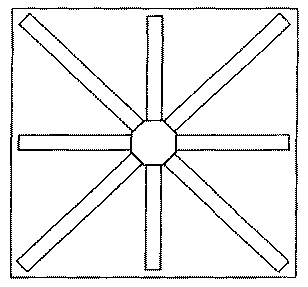
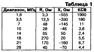
The antenna has dielectric guys, the lower ends of which are fixed on the edges of the roof of the elevator shaft, and the upper ones - at the upper end of the pipe (approximately at the level of 1/3 of the antenna height). The counterweight is made of eight steel strips 180 mm wide, inscribed in the size of the roof of the elevator shaft 2,5x2,5 m (Fig. 2). Antenna weight - 58 kg. In table. 1 shows the measured input impedance and SWR of such a pin on various amateur bands (for a 50 Ohm feeder impedance).
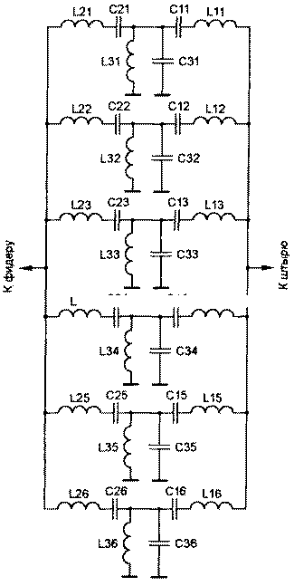
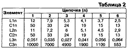
On the 1,8 and 3,5 MHz bands, the antenna almost does not radiate, and on most other bands, its own SWR is too high for it to work effectively. The task of matching the antenna with the feeder is solved by a non-tunable matching device, the diagram of which is shown in Fig. 3. The calculated values of the circuit elements are given in table. 2 (L - in μH, C - in pF). Significant currents and voltages develop in the matching device circuit elements, therefore it is desirable to use K15U-1 ceramic capacitors and single-layer cylindrical inductors made of a copper tube or large diameter wire. The coils must be able to adjust the value of the inductance within ± 20% (for example, using a movable clamp). The dimensions and power of the elements are selected depending on the power of the transmitter with which the antenna will work. The matching node is made as follows. In each of the six chains, the input impedance of the antenna is matched with the wave impedance of the feeder at the middle frequency of the corresponding range (the first chain is at a frequency of 7,05 MHz, etc.). Coordination is carried out as if by an L-shaped link (direct or reverse - depending on the value of the active part of the input conductivity of the antenna at a given frequency), containing an inductance in the series branch and a capacitance in the parallel one. In fact, the indicated inductance and capacitance are obtained by increasing L1 p or L2n and C3p of the L1nC1n, L2nC2n, L3nC3n circuits, initially tuned to resonance at the middle frequency of the corresponding range (has values from 1 to 6 depending on the range) The purpose of these circuits is to weaken the mutual influence chains on top of each other so that the process of alternately matching the antenna on different bands is possible. The matching device works like this. Suppose a signal is received from the transmitter with a frequency equal to the middle frequency of the first range. Let us first assume that the characteristic impedances of circuits 2-6 are very large (i.e., the inductances in them are large, and the capacitances are small). In this case, the input impedances of chains 2-6 will also be very large and will not have a significant effect on the setting of the first chain. The active resistance of the antenna in the first range is less than the wave impedance of the feeder (50 Ohm), therefore, it is possible to match the antenna with the feeder using an L-shaped circuit that has a series inductance on the antenna side and a parallel capacitance on the transmitter side. The L21C21 circuit is tuned to resonance, its resistance is zero, so it seems to be non-existent. In the first chain, the value of the inductance L11 is greater than the value of the inductance L21 by the value necessary to match the input impedance of the antenna to the feeder. In the parallel branch, the value of the capacitance C21 is also greater than the value necessary to tune the circuit L31C31 into resonance by the value that ensures the matching of the antenna with the feeder. With a slight deviation of the frequency from the resonance, the resistance of the L21C21 circuit will be small, and the resistances of the L11C11 and L31C31 circuits will only slightly differ from the values \uXNUMXb\uXNUMXbnecessary to match the antenna at this frequency. In fact, the value of the characteristic resistance of the circuits of the circuits 2-6 cannot be made very large, both for design reasons and because of the need to provide sufficient bandwidth for the 2-6 ranges. Therefore, chains 2-6 affect the level of agreement. This effect is compensated by a corresponding change in the values of L11 and C31. The operation of the matching device on the remaining ranges is similar, with the exception of those on which the active part of the input impedance of the antenna is greater than the wave impedance of the feeder. At the middle frequency of the corresponding range, the resistance of the circuit L1nC1n is equal to zero, and the matching is carried out by changing the values of L2n and C3n. The matching device is configured as follows. First, the values of the elements are set close to the calculated ones, and the circuits L1nC1n, L2nC2n, L3nC3n are tuned to the average frequencies of the corresponding ranges. At the same time, the minimum value of the impedance of the circuits L1nC1n and L2nC2n and the maximum - for L3nC3n. By changing the values of 1_1n or 1_2n and C3n, the actual tuning is carried out at the middle frequency of the range, and it is recommended to start tuning from the lowest frequency range. Since the presence of contours does not completely eliminate the mutual influence of settings on different ranges, the tuning process has to be repeated. To expand the tuning band (reduce the SWR at the edges of any range), you should increase the inductance L3n in the corresponding circuit. To reduce the mutual influence, on the contrary, it is necessary to reduce the inductance L3n, while maintaining the resonant frequencies of the corresponding circuits. With small values of the inductance of the coil L3n, it is performed in the form of a loop. It is desirable that the physical dimensions of the elements be small. Adjustment is recommended to be made at the place where the antenna is installed. Technically, this is not difficult, since the matching unit is located at the base of the antenna. After adjusting the position of the adjusting elements, they are fixed (for example, by soldering) and are not changed later during operation. The SWR at the "resonant frequency" of the antenna for different bands is in the range of 1,2-1,7, and only on the 18 MHz band is it higher - 2,2. Literature
Publication: N. Bolshakov, rf.atnn.ru
Machine for thinning flowers in gardens
02.05.2024 Advanced Infrared Microscope
02.05.2024 Air trap for insects
01.05.2024
▪ Ultra-bright, high-performance Toshiba white LEDs ▪ In addition to bananas, corn may also disappear ▪ Share of renewable energy sources in Brazil - 88,8%
▪ section of the site Tools and mechanisms for agriculture. Article selection ▪ article Space emergencies. Basics of safe life ▪ article What is a protozoa? Detailed answer ▪ article Foxglove rusty. Legends, cultivation, methods of application ▪ article Energy-saving photorelay. Encyclopedia of radio electronics and electrical engineering
Home page | Library | Articles | Website map | Site Reviews www.diagram.com.ua |


 Arabic
 Bengali
 Chinese
 English
 French
 German
 Hebrew
 Hindi
Hindi Italian
 Japanese
 Korean
 Malay
Malay Polish
 Portuguese
 Spanish
 Turkish
 Ukrainian
 Vietnamese
 Leave your comment on this article: