|
|


 Arabic
 Bengali
 Chinese
 English
 French
 German
 Hebrew
 Hindi
Hindi Italian
 Japanese
 Korean
 Malay
Malay Polish
 Portuguese
 Spanish
 Turkish
 Ukrainian
 Vietnamese
|
ENCYCLOPEDIA OF RADIO ELECTRONICS AND ELECTRICAL ENGINEERING The concept of designing modern tube ultrasonic frequencies. Encyclopedia of radio electronics and electrical engineering
Encyclopedia of radio electronics and electrical engineering / Tube Power Amplifiers The new concept, thanks to which the appearance on the European and American markets of modern tube ultrasonic frequencies, which, as it seemed until recently, forever into the past, became possible, is paradoxical in itself. Indeed, everything that was previously considered secondary, insignificant, or even not worthy of attention at all, has now become not only paramount, but essentially determining; and vice versa, what was previously put at the forefront when creating radio equipment (especially household equipment) containing ultrasonic frequency is now generally swept aside as third-rate, if not absurd. In order to make sure that this is indeed the case, let's brush up on the requirements that were once imposed on the low-frequency part of any radio engineering devices. The first and most important of these was economy. The amplifier was required to draw as little power as possible from the power supply. A lot was sacrificed for this: for the terminal cascade, for example, class A mode was regarded almost as criminal, and class AB2 was given preference over class AB1 wherever the clear factor allowed it. In second place were the requirements for the mass and overall dimensions of the main components of the amplifier, in the first place - the output and transition transformers. They were followed by the requirements for maximum manufacturability of production, especially winding units, and ease of installation. The number of lamps and parts in the UZCH should ideally tend to zero, and there was no question of using parts with a 5% tolerance. Today, the only criterion for the viability of a modern tube amplifier is its quality. Everything else without regret is brought to please this indicator. Such concepts as profitability, weight, overall dimensions, cost, complexity of production are recognized as insignificant. No technological difficulties are considered difficulties. The repeatability of two devices descended one after another from the assembly line is declared optional, and the assembly line process itself is called into question. The use of parts with a 5% tolerance, as before, is out of the question, but for a different reason: most resistors should be with a tolerance of no more than 1%. In the output transformer, the spread in the number of turns of the primary windings is limited to half or even a quarter ... of a turn, and it is forbidden even to talk about the spread in the values of their inductances. With regard to the size of the output transformers, the formula is welcomed: "the more - the better." The names of all amplification classes, except for A, are deleted from the lexicon of designers, even if we are talking about 50 or 100 W final stages. The use of semiconductor devices in amplifiers is declared undesirable, and even in rectifiers, kenotron lamps are preferred over silicon diodes. The latter, as an exception, are allowed to be used in rectifiers ... lamp filament circuits. Each newly built amplifier is individually adjusted and tuned like a good concert grand piano, with individual tube selection taken for granted. When choosing the types of lamps for the final stages, it is considered normal to stop at such "prehistoric" direct-heated triodes as 2AZ, if their parameters meet the requirements of the designer. From what has been said, it is clear that it makes no sense to talk about such concepts as efficiency or cost of such ultrasonic frequencies. Indeed, even a relatively "average" 20-watt ultrasonic frequency converter can consume 120 ... 150 W from the network and cost $ 1500 ... 2000 without an acoustic system. So who is this equipment designed for and why is it needed? In the last two or three years, in the Western and American markets for consumer radio equipment, the demand for modern tube ultrasonic frequencies (as independent products), despite their fabulous cost, has not been satisfied. This is explained not only by fashion, although it plays an important role in creating the "tube boom", but also by the unusually high quality indicators of modern tube amplifiers (although achieved at a high price), surpassing transistor equipment of a similar class in subjective comparisons. However, taking into account that "the West is not a decree for us," let's return to Russian reality and see what is the point for us to return to problems long buried and well forgotten. Here it is worth mentioning several reasons. The first of them is the need to draw the attention of our radio amateurs to fundamentally new opportunities that open up when using tube circuits; the second is the most exciting opportunities for creativity and the search for new, original circuit and design solutions. And finally, the third, almost decisive consideration is the ability to independently create a super-fashionable modern and really magnificent amplifying-acoustic complex, which will become the subject of your pride and the black envy of your music lovers. This concludes the general discussion and proceed to the description of several specific amateur designs of tube ultrasonic frequencies and acoustic systems for them. Element base radio tubes Divide the radio tubes into three groups: 1) for terminal and driver (pre-terminal) cascades; 2) for pre-amplification stages; 3) for rectifiers. The first group includes triodes that have a fairly extended linear part of the anode-grid characteristic when operating in class A, as well as powerful beam tetrodes or (less often) pentodes that provide non-linear distortions of no more than 0,5% in an ultralinear switching circuit (of course, also in class A). It makes no sense to list all types of lamps used by Western companies in the final stages, since the possibility of acquiring them is unlikely. However, the parameters of some of them are given in Table. one. Consider those types of domestic-made lamps that can actually be purchased. For most of the lamps mentioned, all the necessary parameters and graphs of typical anode-grid characteristics necessary for a radio amateur are given, for some of the lamps we restrict ourselves to a table (Table 1) of their main parameters. The pinouts and overall dimensions of the lamps are shown in fig. 1 and 2. So, lamps for final stages: a) 2C3 (American analogue 2AZ) - a powerful direct-heated triode (2 V), providing a useful power of at least 20 W in a push-pull transformer cascade in class A; b) 6С4С - almost a complete analogue of the 2C3 lamp, but with a direct glow (6V); c) 6С6С (American analogue 6B4G) - a complete analogue of the 2AZ lamp, but with indirect heating (b C). These three types of triodes are used in the final cascades by almost all foreign companies that produce tube ultrasonic frequencies. For domestic radio amateurs, given the difficulties in acquiring these lamps, several modern triodes can be recommended. These are triodes 6S19P and 6S56P. They are intended mainly for voltage stabilizers as controlled lamps, in most cases they are quite suitable for UZCH terminal stages, although they give less useful power. At the same time, the lamps of this group have an important advantage: they operate at a lower anode voltage, which greatly simplifies the design of the rectifier. If you want to get a large output power, it is quite acceptable to use two lamps connected in parallel in each push-pull arm. The domestic double triode of the 6H13C type (its full American analogue -6AS7-GT) can also be attributed to the same group of terminal triodes, each triode of which allows dissipation power at the anode up to 13 W. It also operates at low anode voltage (90V). If both triodes of one cylinder are connected in parallel, then using two such lamps (two cylinders) in the final stage, you can get a useful output power of over 20 watts. Table 1. Main parameters of tubes used in amplifiers
The choice of powerful beam tetrodes and terminal pentodes for the output push-pull stage according to the ultralinear switching circuit seems to be more modest (in the usual switching circuit, they are practically unsuitable for modern ultrasonic frequencies). Here, German lamps EL-34 and EL-12 can be considered the best. The complete domestic analogue of the first of them is the 6P27S lamp; there is no analogue of the second among either domestic or American lamps. Finally, it is permissible to use a 6P41S lamp specially designed for frame scanning devices for color TVs. As for the output "linear" lamps of all types of TVs, due to their extremely low efficiency, they are of little use for working in class A. In fairness, it should be said that the stereo UZCH developed at the time by the author of this book, intended for the Temp-5 television and radio combine , which received the "Grand Prix" and the Big Gold Medal at the World Exhibition in Brussels in 1958, had in the final stage ... precisely "linear" lamps of the EL-36 type (6P31S). If a radio amateur is satisfied with an undistorted output power of 10 W (which, in our opinion, is more than enough for any residential apartment), it is best to use the EL-84 terminal pentode, the most common in world and domestic practice, a complete analogue of which (apart from reliability and durability ) is a domestic lamp 6P14P. The situation is much simpler with the second group of lamps for phase-inverted, pre-terminal cascades and pre-amplification cascades. The vast majority of Western manufacturers of modern tube ultrasonic frequencies limit their range to four types. Two of them are representatives of more "ancient" series. These are American 8-pin octal double triodes of types 6SN7-GT and 6SL7-GT, which are analogous to domestic lamps 6H8C and 6H9C. The other two are Western European fingertip double triodes of the ECC-87 and ECC-83 types, to which domestic lamps 6N1P and 6N2P are close in terms of parameters. In addition, specifically for the input (first) stages of pre-amplification, it is possible to recommend high-frequency single triodes of the 6S3P and 6S4P types, which were not previously used for this purpose, and are designed to amplify and generate microwave signals. This is due to the fact that these triodes are characterized by a low level of intrinsic noise (the equivalent resistance of internal noise is not more than 170 ohms) and negligible leakage currents in the filament-cathode circuit.
This circumstance is extremely important to achieve the overall level of self-hum and ultrasonic noise at the level of -70 ... -80 dB. More details about the physics of the background in the first stage of the amplifier will be discussed in the section on the design of specific ultrasonic frequencies. And finally, the third group - lamps for rectifiers. At first glance, it may seem absurd to use kenotrons today, when there are a huge number of silicon diodes and diode assemblies that not only completely replace kenotrons, but also have incomparably better performance and efficiency. Nevertheless, not a single Western company uses semiconductors in power supplies for tube amplifiers, preferring tubes. This is explained by the need to prevent the appearance of high voltage on the anodes of lamps (primarily high-power output lamps) until their cathodes are heated to a temperature that ensures the appearance of a rather dense electron cloud around the cathode. Neglect of this requirement very soon leads to "poisoning" of the cathodes of high-power lamps, to their premature aging and failure.
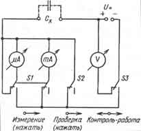
The range of used kenotrons is relatively small and includes the following types: 5TsZS, 5Ts8S, 5Ts9S. Of the American lamps, the most common are 5U4G, 5Y3G, 5V4G, and from Western European lamps - EZ-12. For lamps of all cascades (and especially terminal ones), only ceramic, not plastic, panels should be used. The panels of the lamps of the preliminary stages of amplification must have a protruding flange, on which a metal cylindrical screen is put on from the outside, protecting the lamp from external pickups. For input stages, it is desirable that this screen is not aluminum, but iron (it can be made from galvanized iron sheet roofing). Transformers and chokes. Next in importance after the lamps can be considered all types of winding parts, which include output, transitional and power transformers, as well as power filter chokes. Let's dwell on the principles of their manufacture, common to all varieties, and start with materials for magnetic circuits. For output transformers of low-frequency channels (if the amplifier is two-channel), it is best to use tape, O-shaped magnetic circuits, which allows all windings to be completely symmetrical (for example, two halves of the primary winding of a push-pull end stage are placed on two "halves" of the magnetic circuit). This ensures the maximum identity of their inductances with a strictly identical number of turns. The thickness of iron sheets should be no more than 0,35 mm. The use of iron with a thickness of 0,5 mm for output transformers is unacceptable. If, nevertheless, a magnetic circuit of prefabricated plates is used, then each of them must be lacquered on both sides in order to minimize losses due to Foucault currents. The same applies to jumper plates. If the amplifier is two-channel, then for the high-frequency channel for winding the output transformer, it is best to use a ferrite magnetic circuit from the horizontal-scan output transformer of old tube TVs (transformers of the TVS-110 type). More details about the manufacture of transformers will be discussed later. The easiest way is to use a ready-made industrial power transformer from old tube TVs. For this purpose, transformers from Temp-6 (6M, 7, 7M) TVs are suitable, since they practically do not need to be modified. The kinescope filament winding available on such a transformer can be used to heat the lamp of the first (input) stage of the amplifier, the common filament winding can be used to power the filament (through a separate rectifier) of the lamps of the remaining stages. True, when using this transformer, which has an asymmetric secondary winding, you will have to use an anode rectifier, a detailed description and diagram of which are given in the "Power Sources" section. In an ultrasonic frequency converter with an output power of more than 40 W, it is better to put a ready-made power transformer from the KVN-49 TV or make a similar transformer yourself according to the data given at the end of the book. If the output power does not exceed 20 W, power transformers from old tube receivers "Minsk-55", "Minsk-R7", "Neva-51 (52, 55)", "October", "Riga- T689", which will have to be redone. To ensure high quality, a transformer with the necessary parameters can be made independently. Rectifier filter inductors are better, and the easiest way is to use factory ones, preferably from TVs "Temp-3 (6, 7)", "Rubin-102", "Avangard", "Belarus", or make them according to the data given below. Fundamentally new for the readers of this book may be the requirement that the filter chokes must be tuned to resonance at a frequency of 100 Hz. This is necessary to improve the filtering efficiency of the rectified voltage. The most labor-intensive in the manufacture of output transformers. Here it will not be possible to use any standard transformer from industrial receivers and televisions, and they will have to be completely done independently, starting from a special frame for windings and ending with external screens. This work is time-consuming and painstaking, requires a lot of attention and patience, and also requires the presence of special equipment and devices (first of all, a winding machine with a coil-to-coil wire stacker and an accurate counter of the number of turns). Therefore, the description of the manufacture of output transformers will be given special attention. Capacitors The requirements for capacitors and resistors designed for use in modern tube amplifiers are significantly different from those for conventional consumer radio equipment. Let's start with capacitors, and first of all with transitional or separating ones, connected between the anode of the lamp of the previous stage and the control grid of the next one. As a rule, a rather high direct voltage (100 ... 300 V) is applied to the plates of such a capacitor, so the first requirement for them is the corresponding operating voltage, which should be at least 30 ... 50% higher than actually applied in the circuit , i.e. have a passport value of 250 ... 500 V. The current generation of radio amateurs, brought up on a semiconductor element base, has already managed to wean itself from such values of operating voltages, so special attention should be paid to this parameter. But the main requirement for transitional (separating) capacitors is the inadmissibility of any noticeable leakage. In order to make this clear, we recall that the transition capacitor is connected at one end to a 200 ... 300...0,5 MΩ. Even if the capacitor leakage current is only 1 µA, then it will create a voltage drop of 1 V across a 1 MΩ resistor, and this will shift the operating point of the lamp also by 1 V on the characteristic, which will make the very idea of \u1b\uXNUMXbcreating a high-quality amplifier meaningless. Therefore, without exception, all capacitors for transient circuits must be preliminarily checked and selected according to this parameter. To do this, the reader will have to assemble the device according to the scheme shown in Fig. 3, and with its help to carry out individual selection, having subjected to sorting, perhaps, more than a dozen capacitors.
Attention! Caution 1 Since the leakage current is very small in absolute value, it is necessary to use a galvanometer to measure it. And in order not to accidentally disable this highly sensitive and expensive device, you must strictly adhere to the following procedure: 1. Set switch S3 (see diagram) to the "Control" position. 2. Check the test capacitor with a tester for the absence of a short circuit (breakdown). 3. Connect the capacitor to the "Systest" terminals. 4. Connect a high voltage to the "U-" terminals (300, 400 or 500 V, depending on the operating voltage of the capacitor) and check the voltage value on the voltmeter scale. 5. Switch S3 to the "Operation" position. 6. Not earlier than after 30 s, press the S2 button and look at the scale of the milliammeter, the arrow of which should not deviate by a single division, after which the button should be released. 7. Press button S1 with your left hand, then, without releasing the first button, press button S2 with your right hand and determine the leakage current of the capacitor on the galvanometer scale. Caution 2 If in paragraph b the arrow of the milliammeter deviated from zero even by an insignificant amount, in no case do not press the S1 (galvanometer) button, and put the capacitor aside as unsuitable for use in your ultrasonic frequency converter. What is the best type of capacitor to use? This question is very difficult, because most transition capacitors should have a capacitance of 0,1 ... 0,5 μF at an operating voltage 300 ... 400 V. Most often these are paper or metal-paper capacitors, namely, they, as a rule, have a large leakage current. It is believed that capacitors with fluoroplastic, polystyrene and polypropylene insulation have the best insulation (and, consequently, the lowest leakage current). However, most radio amateurs are not able to determine the type of capacitor insulation either by its appearance or even by marking. Therefore, we offer a choice of the most suitable types from among those produced by the domestic industry. These are the types: KM-3 0,22 uF 250 V; K10-47 0,1...1,0 uF 250 and 500 V; K73-9 0,1...0,15 uF 400 V; K73-11 0,1...1,0 uF 400 V; K73-15 0,1...0,22 uF 250 and 400 V; K73-16 0,22...1,0 uF 400 V; K73-17 0,1...1,0 uF 400 V; K78-2 0,1 uF 300 V; K78-4 0,47...1,0 uF 500 V; K78-6 0,12...1,0 uF 400 V. For low-voltage circuits (for example, in devices for volume and tone control, loudness, frequency-dependent feedback, etc.), the choice of capacitor types is less critical in relation to leakage current and practically does not limit the designer. At the same time, for these circuits, the requirement for a minimum deviation of the actual capacitance from the specified nominal value comes to the fore, which is not essential for coupling capacitors. It should be noted that sometimes the absolute value of the capacitance of the capacitor is not so important (it may well differ from that indicated on the diagram even by 10%), as the same actual capacitance of two capacitors in two circuits of the same name in a symmetrical circuit. Rectifier filter capacitors or oxide capacitors in the cathode circuits of lamps have the least stringent requirements. Any available types can be used, as long as they provide a sufficient margin for the operating voltage and are suitable in size and method of fastening. It must be recalled that in some units (for example, in a doubler rectifier), some capacitors have an ungrounded negative terminal, which is usually connected to the capacitor case. In these cases, the case of such a capacitor must be reliably isolated from the case of the amplifier in order to completely eliminate the possibility of accidental short circuit or high voltage shock. Resistors When choosing resistors, a radio amateur who is used to working with transistors will face two new problems for him. First, unlike most transistorized tube amplifier circuits, where all tubes operate in class A and therefore consume noticeable (sometimes significant) power, the power rating of the resistors becomes significant, so further in the circuits you will often meet with power designation 0,5; 1,0; 2,0 and even 5,0 and 10,0 watts. Pay due attention to these designations. It is best to use resistors of the MLT (OMLT) types with tolerances of 2 and 5%, C2-ZZN with tolerances of 1, 2 and 5%, P1-4 with tolerances of 1, 2 and 5%, C 1-4 with a power of 0,5 W and tolerances of 2 and 5%. It would be ideal to use precision resistors of types C2-14 or C2-29V with tolerances of 0,25 ... 1,0%, covering the entire scale of resistance from 10 Ohm to 5,1 MΩ and powers from 0,125 to 2 W, but this be difficult. As resistors with a power of more than 5 W, it is best to use types C5-35V (old designation PEV), C5-37 with tolerances of 5% or precision types C5-5 and C5-16 with tolerances of 0,5 ... 2,0%. The second, more significant point is the allowable spread of absolute values. Unfortunately, we have to state that in some circuits the use of resistors with a tolerance of 1-2% is required. It can be argued that most radio amateurs will not have such resistors in their assortment. Therefore, the author proposed a compromise, consisting in the fact that instead of one precision resistor, in certain critical cases, a "coupling" of two resistors connected in series is provided in the circuits and on printed circuit boards. In this case, the resistance of one (main) resistor is chosen slightly less than the specified one, and its disadvantage is compensated by selecting the resistance of the second resistor. Let's explain the above with an example. Let the diagram indicate the total resistance of the coupling 110 kOhm with a tolerance of 1%. In this case, from several resistors of the specified rating, using a tester (better - a digital ohmmeter), we select a resistor, say, 105 or 108 kOhm and, in addition to it, from another group with a nominal value of 5,1 or 2,0 kOhm, a resistor having a resistance of 5 or 2 kOhm This is certainly easier than finding a resistor exactly 110 kΩ. However, one should not be afraid in advance: in the circuit there are usually only a few resistors, the resistance of which is so critical. In most other cases, a spread of 5 is quite acceptable, and in some circuits up to 10%. With regard to variable resistors, the greatest difficulties are expected when using dual and paired volume and tone controls in stereo amplifiers. Their main drawback is that in the position of the minimum value (the axis is all the way to the left), the transition of the slider from the graphite coating to the metal base for two potentiometers does not occur simultaneously: for one - a little earlier, for the other - a little later, as a result of which, for example , the volume in one of the channels disappears completely, and in the other - no. For a modern tube amplifier, this is considered absolutely unacceptable. If you're unlucky and you can't find sufficiently identical dual potentiometers, you'll have to modify them. The refinement will come down to the fact that in one of the two dual resistors (and most likely in both) this defect will have to be corrected purely mechanically - by bending the current collector bow, if the design allows it, or by mutual, towards each other, displacement of the platforms carrying the current collectors. In addition, to ensure a longer service life and prevent rustling and crackling, all without exception operational controls (volume, tone, stereo balance) must be opened before installation in the amplifier, wipe the working (current-carrying) part with alcohol or pure gasoline (but not automobile, and even so no longer with a solvent or acetone!), then evenly lubricate with clean technical petroleum jelly (you can use it for children, but by no means cosmetic!), carefully and tightly close the covers again, and drop one (no more!) Drop into the gap between the axle and the bushing machine or transformer oil. As installation and adjustment variable resistors, which will have to be used extremely rarely, mainly during the initial adjustment and tuning of the amplifier, it is best to choose dust- and moisture-proof ones, with reliable contact between the current collector and the working surface of the bow (for example, types SPZ-9, SPZ- 16, SPZ-45b, SP4-2M-b or wire interlinear types SP5-16V-b and SP5-2V). Semiconductor devices. It was previously noted that in modern tube amplifiers, transistors and diodes are practically not used by any of the manufacturing companies. The fact is that tube amplifiers produced by Western companies, as a rule, are either an independent powerful terminal block with a linear frequency response, a standard input (1 or 10 V at a load of 600 Ohms), an output of 20, 40, 50 or 100 W at 4 or 8 ohm load without any controls and indicators, or full UF (mono or stereo - both are equally common) with switched inputs for standard sound sources, volume control and two tone controls. In stereo amplifiers, in addition, sometimes there is a stereo balance control. And it's all. No EQs, LED signal level indicators, overload alarms, expanders (dynamic range extenders) - nothing but a really great high-end amplifier. And in such an amplifier, transistors are really useless. In our case, we are not dealing with industrial developments, but with designs that each reader of this book will make in a single copy. Therefore, it will be not only permissible, but justified to complicate the design by introducing some service additions into it. These include a block of advanced tone controls (in four sections of the operating range), a system for indicating the maximum undistorted level of the output signal, an electro-optical device for accurately setting the stereo balance based on a real signal, and a number of others. And since all these service devices do not affect the process of amplifying low-frequency signals, it is quite reasonable to perform them on transistors and semiconductor diodes, and not on additional lamps, which we will reluctantly do. Literature 1. High quality tube ultrasonic frequencies Author: tolik777 (aka Viper); Publication: cxem.net
Machine for thinning flowers in gardens
02.05.2024 Advanced Infrared Microscope
02.05.2024 Air trap for insects
01.05.2024
▪ Converting coal to anode grade graphite ▪ Internet for robots predicted explosive growth ▪ A new way of light propagation in glass
▪ section of the site Reference materials. Article selection ▪ article From gulkin's nose. Popular expression ▪ article Which hemisphere of the brain is more developed in creative people? Detailed answer ▪ article Nail, bar and gramophone record. Focus Secret
Home page | Library | Articles | Website map | Site Reviews
www.diagram.com.ua | |||||||||||||||||||||||||||||||||||||||||||||||||||||||||||||||||||||||||||||||||||||||||||||||||||||||||||||||||||||||||||||||||||||||||||||||||||||||||||||||||||||||||||||||||||||||||||||||||||||||||||||||||||||||||||||||||||||||||||||||||||||||||||||||||||||||||||||||||||||||||||||||||


 Leave your comment on this article: