|
|


 Arabic
 Bengali
 Chinese
 English
 French
 German
 Hebrew
 Hindi
Hindi Italian
 Japanese
 Korean
 Malay
Malay Polish
 Portuguese
 Spanish
 Turkish
 Ukrainian
 Vietnamese
|
ENCYCLOPEDIA OF RADIO ELECTRONICS AND ELECTRICAL ENGINEERING UMZCH Kindtree-A140m on a TDA7294 chip. Encyclopedia of radio electronics and electrical engineering
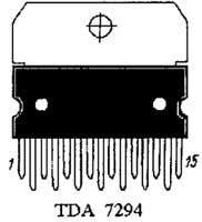
Encyclopedia of radio electronics and electrical engineering / Transistor power amplifiers The prehistory of this amplifier is connected with an amplifier I once made on an integrated STK chip, which later burned out ... In this regard, I chose a chip with built-in protection TDA 7294. Of course, not the ultimate dream of lovers of high-quality sound, but still. This microcircuit, along with its shortcomings, has a number of advantages for its implementation at home, namely:
Amplifier Specifications:
Purpose of the amplifier: Amplifier made on a microcircuit TDA 7294 universal for use, mainly at home. It has screw terminals for connecting acoustics, the input signal is fed to the amplifier through "tulips".
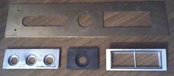
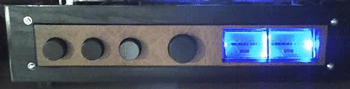
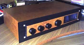
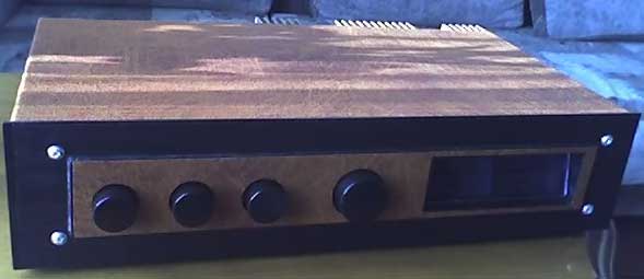
Amplifier assembly description (case) For the manufacture of the case, the following was required: Front Panel;
All joints were puttyed with auto-filler, removed with sandpaper and painted.
Then analog signal level indicators were installed.
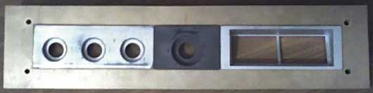
So, the front panel is ready:
Chassis used old. It has a stepped volume control, bass/treble and balance controls, a 150-watt toroidal transformer, and a preamplifier board. It is also interesting that the sound regulator is installed through gears, which provides smoother regulation.
The case cover from the previous amplifier was pasted over with a vinyl film in the color of a tree (hence, by the way, this strange name of the amplifier :)) Rear wall made of textolite:
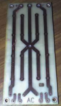
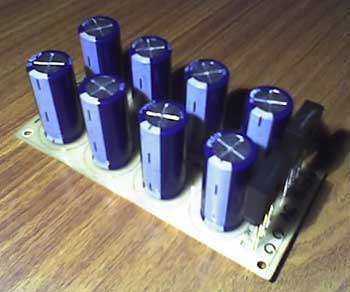
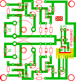
Amplifier assembly description (circuit boards) 1. Power supply board It was made according to the traditional bipolar power supply scheme, using 4 electrolytic capacitors, each with a capacity of 4700 microfarads. Diode bridges, with a transmission current of up to 8 A in the arm, because the microcircuit requires no more than 4A, cooling of the diode bridges was not required. The printed circuit board of the power supply:
The total capacitance turned out to be 18800 uF in the shoulder, more than enough for such an amplifier. From below, the capacitors were shunted with non-polar ones, with a capacity of 2,2 μF, and at the output, 0,1 μF. Dischargers were not installed.
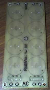
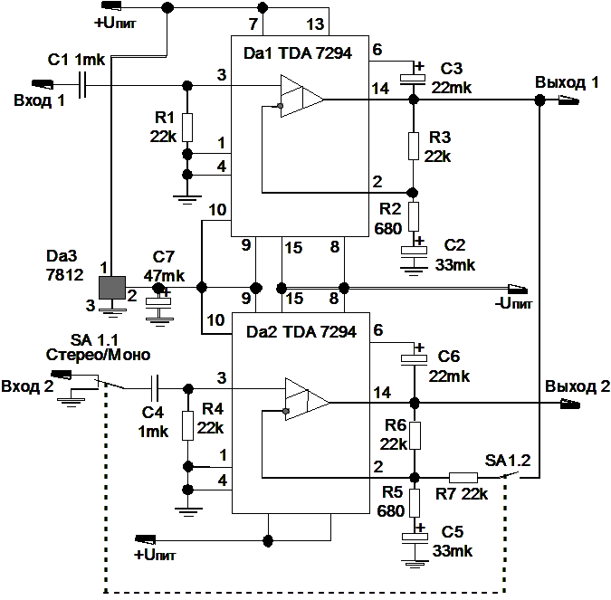
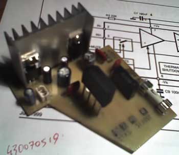
2. Amplifier board Changes have been made to the board regarding the input path. The modernization consisted in providing the ability to install "sound" feed-through capacitors on the circuit. Electrolytes were taken with normal temperature characteristics (1050C) A voltage stabilizer chip (12 V) installed on the radiator in a plastic case.
Schematic diagram
The SA1 toggle switch is required to switch the amplifier to bridged mode, while its power increases to 150 watts. 3. Analog indicator board Printed circuit board This board was made on two 315 transistors, and requires a 27 V supply. the voltage supplied to it from the power supply is 27V; instead, you can put a KS35A or D527B zener diode.
Schematic diagram The diagram shows the connection for only one indicator. The photo with the printed circuit board (see above) shows the connection (mirror) for two indicators, because The amplifier has two channels.
View of analog indicators in the amplifier case, with neon illumination
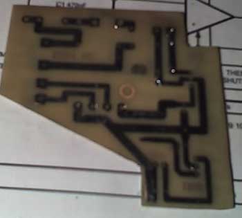
4. Distribution board Printed circuit board
The meaning of this device is as follows: It is supplied with voltage from the mains, which then, after passing through the fuses, and a filter in the form of a 10 nF / 400V capacitor, is supplied to the primary winding of the transformer. From the secondary winding of the transformer, an alternating voltage of 15V is supplied, which goes to the diode bridge, and is distributed to provide power to the equalizer and backlight analog indicators using 12V and 5V voltage stabilizer microcircuits, respectively. The latter are located on a common radiator.
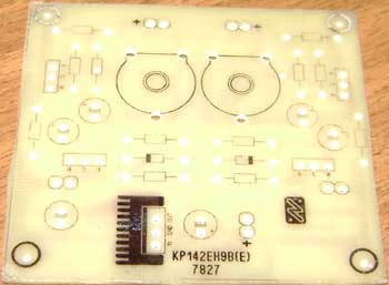
5. Equalizer board Printed circuit board
The board provides two-channel adjustment of sound, balance, low and high frequencies. Variable resistors can be used any, because. volume, balance and timbre in this microcircuit is carried out electronically. Trimmer resistors R7 and R8 regulate the gain of the output signal, the button S1, which turns on the frequency compensation of the volume control (off in the diagram), must be latched. For those who want to constantly use frequency compensation without the possibility of turning it off, elements S1 and R9 can be excluded from the circuit. During operation, the microcircuit heats up. Glue to it (for example, with Moment glue) a small U-shaped aluminum radiator. This will increase the reliability and service life of the microcircuit. PS Loudness compensation for some reason turned out to be non-working. Schematic diagram
Regulator Specifications Frequency band 20-20 000Hz
In the end, having collected all of the above in one heap, it turned out to be a good amateur amplifier.
Author: Oleg Nikulin (liveofsou@mail.ru); Publication: cxem.net
Machine for thinning flowers in gardens
02.05.2024 Advanced Infrared Microscope
02.05.2024 Air trap for insects
01.05.2024
▪ MCP1810 - Lowest Iq LDO in the industry ▪ TI OPT3101 Optical Ranging Chip ▪ Insects can generate electricity ▪ 48-core Cavium ThunderX processors
▪ section of the site Standard instructions for labor protection (TOI). Selection of articles ▪ article Lamarck Jean-Baptiste. Biography of a scientist ▪ article Funeral service worker. Job description ▪ article MicroTV Cornflower. Encyclopedia of radio electronics and electrical engineering
Home page | Library | Articles | Website map | Site Reviews
www.diagram.com.ua |


 Leave your comment on this article: