|
|
ENCYCLOPEDIA OF RADIO ELECTRONICS AND ELECTRICAL ENGINEERING Chip TDA8362 in 3USCT and other TVs. Encyclopedia of radio electronics and electrical engineering
Encyclopedia of radio electronics and electrical engineering / Телевидение Many families still operate obsolete TVs - ULCT, UPIMCT and even 3USCT. Their owners, having experience in amateur radio design, would like to endow their devices with a number of features inherent in new modern models, improve the quality of the received image and some parameters. This article explains how you can upgrade old TVs using the TDA8362 chip. Mass production of color televisions in our country began in 1973 with the release of a unified lamp-semiconductor model ULPCT and later - ULPCT (I), which were replaced by the UPIMCT series and later - 2USCT and 3USCT. Their annual output in the best years exceeded two million pieces. Even though in 1991 fourth-generation devices appeared, the bulk of production until recent years was 3USCT televisions. It is not surprising that after the collapse of the USSR, the inhabitants of Russia left more than 40 million color television sets, mostly of the first or third generation. All of them, from the point of view of the modern user, are considered obsolete both morally and physically. If the question of the obsolescence of devices is clear, then their physical aging can be judged if we recall that the age of the ULPCT TVs preserved by the population reaches 20 ... 25 years (their production was discontinued in 1978). There are 15-20 million televisions of the UPIMCT (5-6 years old). According to pre-existing norms, the service life of the TV set was 3 years. From this point of view, all the devices ULPCT, UPIMCT and part of the 20USCT have already served their purpose and should seem to give way to new ones. However, articles with proposals for the modernization of old TVs still appear in the Radio magazine and in other literature. And this is good. It is possible and necessary to think about prolonging their life. This is also necessary because the financial situation of many families does not allow them to replace their existing TV with a new one. In addition, at least 10-15 million 3USCT devices have not worked out their due date and can still serve their owners. All this allows us to consider that the problem of modernizing TVs in order to extend the service life, improve reliability and introduce new functions at low costs (no more than 20% of the cost of a new device) is very relevant and remains so for more than one year. One of the ways to solve this problem is the introduction of a modern element base into obsolete TVs. But before moving on to specific proposals, let's look at a little history. Integrated circuits in domestic televisions were first used in 1976. in one of the ULPCT(I) models, in which the BCI color module was used on K224 series microcircuits. Wider use of the microcircuit was found two years later in TVs UPIMTST, when the electronics industry began mass production of the K174 series. Its first devices had a low degree of integration and needed a large number of external radio components. So, ten ten microcircuits in the signal processing unit (BOS) of the UPIMTST TV were accompanied by 440 different parts. By modern standards, this is too much for a radio channel and a color channel. The table published here contains information about the number of parts in the blocks of the radio channel, synchronization, color and output video amplifiers of TVs of different generations. It follows from it that the situation improved slightly with the advent of 2USCT and 3USCT TVs, in which more advanced K174 series microcircuits were used.
However, the number of attachments was still large, which reduced the operational reliability of these most popular TVs. Reliability was also reduced by a large number of adjustment elements for adjustment during production and after repair, and the presence of two dozen pairs of interblock connectors with a hundred contacts. It is no coincidence that TV sets of the fifth or sixth generations clearly showed a trend towards the use of highly integrated microcircuits, which, while expanding the list of functions, preserve or even reduce both their number and the composition of the outer frame, and reduce the number of adjustment elements (points). Numerous connectors are now being eliminated, abandoning the cassette-modular design and returning to the monoblock chassis - the basis of the first industrial and amateur televisions. Where it is impossible to refuse connectors, their new, more reliable models are used. As for microcircuits, in TVs of the fourth or fifth generations, the radio channel and color paths still contain five or six cases and require the same number of attachments as the third generation models. Against this background, multifunctional microcircuits from Philips stand out for the better, allowing sixth-generation TVs to solve circuitry problems more economically and implement a radio path and a color path on three cases while reducing the outer frame by half. These include LSI TDA8362, TDA8375, TDA8396, of which the first is most widely used. It is used not only by leading foreign companies (for example, Panasonic-TX-21S TV, etc.), but also in the CIS ("Horizon-CTV-655", "Electron-TK-570/571", "TVT-2594/2894 "). In some models, not three, but six microcircuits are used, which is explained by the use of integrated video amplifiers that dissipate less power and reduce the number of transistors from 14 to 3. Of course, the TDA8362 chip can also be used in TVs of outdated models when they are upgraded (replacing the radio channel, color and synchronization blocks with more advanced ones). A detailed description of the structure and operating parameters of the TDA8362 chip is given in [1] and [4]. It provides processing of black-and-white and color television signals both at intermediate frequency (IF) and given in the form of color difference and color signals encoded according to SECAM, PAL, NTSC systems. In this case, the IF signals can have, as usual, the negative modulation used, and the positive modulation used in the French standard L. Video signals can be presented in VHS and S-VHS formats. It also processes M (4.5 MHz), B, G, H (5.5 MHz), I (5.996 MHz), D, K, L (6.5 MHz) FM audio and AF audio signals, as well as horizontal and vertical synchronization (the latter at frequencies of 50 and 60 Hz) with the number of lines per frame within 488...722. The implementation of all these functions in one microcircuit is achieved using conventional bipolar transistors for processing analog signals of any frequency and transistors of the MOS structure for solving problems by digital methods. There are several modifications of the microcircuit, differing in the list of implemented functions and pinout. In full, all these functions are provided in the TDA8362A, but the TDA8362 and TDA8362N3 modifications are much cheaper, although they have insignificant differences. An analysis of the capabilities of the TDA8362 chip shows that their use in full in our conditions is not required. Many will consider the ability to process NTSC signals to be superfluous, since on-air programs encoded according to the NTSC-M-3.58 system are not available to our viewers (with the exception of those living in Chukotka and southern Sakhalin). NTSC-4.43 signal processing may only be needed when viewing recordings on video cassettes and video discs made in the USA, Japan and Korea. Of course, it is not required to receive signals in the H, I standards and signals with positive modulation of the SECAM-L standard. However, work according to the specified standards (H, I, SECAM-L, NTSC-4.43) is already provided for in the TDA8362 chip and you cannot refuse them, you can only not use them. Probably, from the above considerations, in [2] a typical scheme for switching on the TDA8362A modification for processing only signals from SECAM, PAL systems and standards B, G, D, K is considered. In accordance with them, a radio channel, color and synchronization module (MRCC) is offered to radio amateurs on TDA8362 chip, adapted for use in a 3USCT TV of any modification. Recommendations will also be given for those who wish to introduce the ability to receive signals from the NTSC-4.43 system into the module and use the module in other types of TVs.
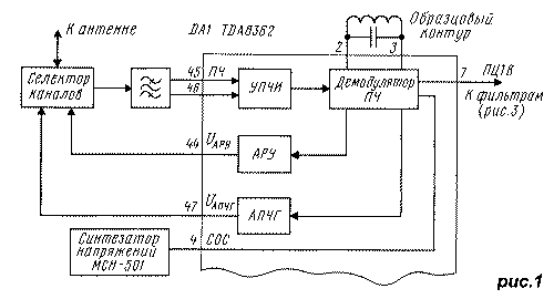
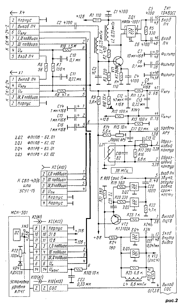
The MRCC module replaces the radio channel (A3) and color (A1) modules with the submodules SMRK (A2), USR (A1.3), SMC (1.4) in 2.1USCT TVs. The cassette-modular design of the chassis of 3USCT TVs simplifies the work of replacing modules, reducing it to removing two boards and installing a new one in their place. The module is powered by 12 and 220V voltage sources available in the TV. The current consumption in the 12V circuit is 160mA (instead of more than 500mA for replaceable modules), which has a beneficial effect on the operation of the rectifier in the TV power module and reduces power consumption. Consider the circuit diagram of the module, starting with its radio path. It includes channel selectors, preamplifier with SAW filter, UPCH, IF demodulator, APCG and AGC devices. A block diagram showing the relationship of these blocks is shown in Fig.1. Figure 2 shows a schematic diagram of the path. Depending on the type of program selection device (UVP), the diagram shows options for connecting the USU-1-15 (SVP-4/5/6) blocks and the MSN-501 synthesizer (drawn with thick lines).
The sensitivity of the TDA8362 chip (DA1 in Fig. 2) at the input (pins 45 and 46) is 100 μV, and according to existing standards, the sensitivity of the TV in subbands I, II should be no worse than 40 μV at the antenna input. Therefore, the transfer coefficient (gain) Kу in the circuit from the antenna input to the microcircuit input must be at least 8 dB. The circuit contains a channel selector SK-M-24 (Kу=15 dB) and SAW filter ZQ1 (Kу < -25 dB). This means that when the selector is connected directly to the filter, the input sensitivity of the TV will be below the norm by at least 18 dB (approximately 320 μV), which is unacceptable. To save it, a pre-amplifier on a transistor VT1 c K is turned on.у > 20 dB, allowing with a small margin to compensate for the attenuation in the ZQ1 filter. Note in passing that Kу Philips' modern UV-917 all-wave selector is at least 38 dB at a very low noise level, which allows you to directly connect it to a SAW filter and at the same time provide twice the sensitivity of the TV. Such a selector is used in the TV set "Horizon - CTV-655". The ZQ1 band-pass filter must meet the following requirements: operate on an IF image carrier of 38 MHz, have a wide horizontal frequency response section ("shelf") in the 31.5 ... 32.5 MHz band and a balanced output. These requirements are met by surfactant filters KFPA-1007, KFPA-2992, KFPA-1040A. The widely used filters KFPA-1008, K04FE001 have a narrow "shelf" and will not provide reception according to standards B, G. The FPZP9-451 filter used in 3USTST TVs has an unbalanced output, which requires the introduction of a balancing cascade between it and the microcircuit on two transistors. After amplification in the UPCH (see Fig. 1), the IF signals in the demodulator are converted into a full color television video signal (PCTV). The demodulator contains a white spot inversion node (limiting PDTV emissions caused by interference) at a medium brightness level, which improves image quality, preventing the appearance of noise on the screen, as well as a sharp change in the amplitude of the PDTV and the sync pulses included in it. Oscillatory circuit L3C18 (see Fig. 2) serves as a common exemplary circuit for IF demodulators and the APCG device, which reduces the number of tuning elements in the module. APCG voltage (UAPCG) at the control point X1N during signal capture can vary within 0.5 ... 6.3 V and with fine tuning of the circuit to a frequency of 38 MHz and the selector to the image carrier, it is equal to 3.5 V. When using UVP type USU, SVP voltage UAPCG enters the selectors through the circuit R12R13R18C10R7C11, where it, adding up with the presetting voltage UMon, coming from the UVP through the resistor R8, forms the voltage setting of the selectors UН. In the case of using the voltage synthesizer MSN-501, the addition of voltages UAPCG with UMon and the formation of UН takes place in the synthesizer. Voltage UAPCG applied to it through the chain R12R13R105C23, and the resulting value UН passes to the selectors from pin 6 of connector X2 (A13) via the R8C11R7C10 circuit. Let's return to the exemplary circuit L3C18. Each TV is characterized by such a feature: in the process of pre-tuning to some program with the APCG device turned off, it turns out that the capture bandwidth of the image carrier when approaching it from the low frequencies is wider than the same band when tuning from higher frequencies. This phenomenon does not arise from poor adjustment of the APCG. It is explained by the fact that, with the correct adjustment of the selectors, the image carrier is located on the slope of the frequency response of the bandpass IF filter (it does not matter if it is a SAW filter in 3USCT TVs or a lumped selection filter in UPIMCT). The slope of the frequency response leads to the asymmetry of the signal applied to the demodulator of the AFCG device, which is especially noticeable at a weak input signal, when the noise level, which is smooth at the input of the channel selector, becomes noticeably asymmetric at the input of the AFCG system. As a result, there is a voltage shift UAPCG from the correct value, which causes the detuning of the receiver and the indicated swath asymmetry. When using the TD8362 chip, measures were taken to eliminate such a defect by including the C19R19 circuit. Voltage UAGC applied to the channel selectors from pin 47 of the microcircuit through the circuit C13R11C12R10R9. Its initial level is set by a tuning resistor R15. From pin 4 of the chip, pin 2 of connector X10 (A13) receives the synchronization identification signal (SOC) used in the voltage synthesizer to control the automatic program tuning system. Signal voltage USOS is equal to zero if there are no synchronization pulses at the input of the microcircuit. Voltage USOS equal to 6 V, if the input receives a signal of the NTSC-3.58 system, or * V, if the "color" or "black and white" signal of the SECAM, PAL, NTSC-4.43 systems is received.
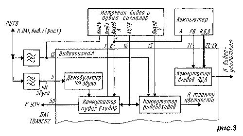
From pin 7 of the PDTV microcircuit, it enters a set of external filters, where it is divided into a video signal and an FM audio signal. Bandpass filters ZQ2, ZQ3 select frequency bands in which FM audio signals are placed (5.5 +/- 0.05 MHz in B, G standards and 6.5 +/- 0.05 MHz in D, K standards). Through pin 5 of the microcircuit, as shown in Fig. 3, they pass to the demodulator, and then to the audio input switch. The FM audio demodulator has a phase-locked loop (PLL) system that provides automatic tuning to any audio standard. Notch filters ZQ4, ZQ5 (see Fig. 2), clearing the PDTV from the bands occupied by FM audio signals, turn it into a video signal, which is fed through pin 13 of the microcircuit to the video input switch (see Fig. 3). Figure 3 also shows the switch R, G, B, we will consider its operation further. Audio and video input switches also receive signals from external sources (VCR, video disc player, video game console). The control of switches (AV/TV function) is ensured by applying the appropriate voltage to pin 16 of the microcircuit: less than 0.5 V to turn on the on-air program (TV); 3.5...5 V to turn on an external program in S-VHS (AV) format; 7.5...8 V for operation from an external source of VHS (AV) format. If there is no voltage at pin 16, the chip operates in TV mode.
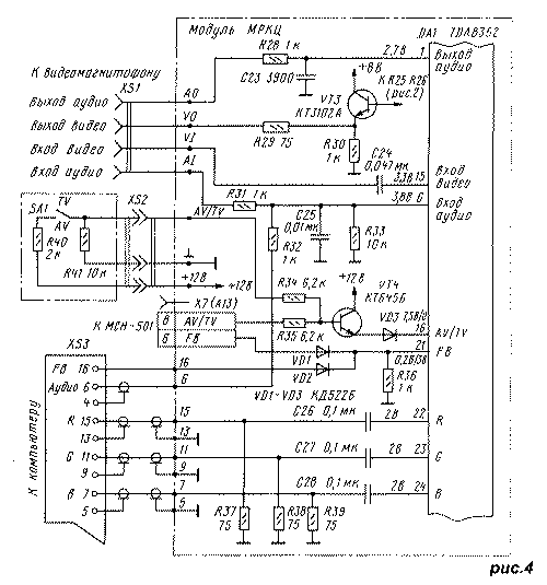
Recall that the recently appeared S-VHS video recorders (for example, Philips-VR969) provide higher image quality (400-430 lines versus 230-270 lines for VHS video recorders and 320 ... 360 lines for on-air programs). This is achieved by placing the color component not in the usual 3...4.7 MHz PDTV band, but in the 5.4...7 MHz band. During playback, such video recorders are connected in three circuits: the audio signal is connected to pin 6 of the microcircuit, the brightness signal S-VHS-Y is connected to pin 15, the color signal S-VHS-C is connected to pin 16. If there is only one external source of video signals in VHS format, then it is connected to the MRCC as shown in Fig.4. When using an MCH synthesizer, the AV/TV signal comes from it through connector X7 (A13). If USU, SVP blocks are used, then you will have to manually receive the AV / TV signal with the SA1 switch in two positions, installed in a convenient place on the TV case. In both cases, in TV mode, a voltage of no more than 0.4 V is generated (or it is absent), and in AV mode, at least 10 V. The latter is transmitted to pin 16 of the microcircuit through a switch on the VT4 transistor. The type of input and output connectors XS1, XS2 is selected depending on the type of their counterparts in the signal source used. If there are several sources of video signals, then they are connected to the MRCC through a matching device. Detailed information on its construction is given in [<3]. Literature
Publication: N. Bolshakov, rf.atnn.ru
Alcohol content of warm beer
07.05.2024 Major risk factor for gambling addiction
07.05.2024 Traffic noise delays the growth of chicks
06.05.2024
▪ Electric motor without magnets ▪ Supercapacitors VINATech VPC ▪ The rich live 9 years longer than the poor
▪ section of the site Car. Article selection ▪ article Vote or lose! Popular expression ▪ article Where was baseball invented? Detailed answer ▪ article Yateoriza digitata. Legends, cultivation, methods of application ▪ article Digital voltage indicator. Encyclopedia of radio electronics and electrical engineering ▪ article Pendulums with a hippopotamus and a bird. physical experiment
Home page | Library | Articles | Website map | Site Reviews www.diagram.com.ua | ||||||||||||||||||||||||||||||||||||||||||||||||||||||||||||||||||


 Arabic
 Bengali
 Chinese
 English
 French
 German
 Hebrew
 Hindi
Hindi Italian
 Japanese
 Korean
 Malay
Malay Polish
 Portuguese
 Spanish
 Turkish
 Ukrainian
 Vietnamese


 Leave your comment on this article: