|
|


 Arabic
 Bengali
 Chinese
 English
 French
 German
 Hebrew
 Hindi
Hindi Italian
 Japanese
 Korean
 Malay
Malay Polish
 Portuguese
 Spanish
 Turkish
 Ukrainian
 Vietnamese
|
ENCYCLOPEDIA OF RADIO ELECTRONICS AND ELECTRICAL ENGINEERING What you need to know about the operation of a three-phase electric motor in a single-phase network. Encyclopedia of radio electronics and electrical engineering
Encyclopedia of radio electronics and electrical engineering / Power supply In repair and amateur practice, it is very often necessary to use three-phase electric motors for a power drive (machine tools, emery and other devices). However, for their power supply it is not at all necessary to have a three-phase network. The most efficient way to start an electric motor is to connect the third winding through a phase-shifting capacitor. In order for a capacitor start motor to work properly, the capacitance of the capacitor must change with the RPM. Since this condition is difficult to fulfill, in practice the engine is controlled in two stages. The engine is turned on with the calculated (starting) capacitance of the capacitor, and after its acceleration, the starting capacitor is turned off, leaving the working one (Fig. 1). The starting capacitor is switched off manually by switch B2.
The working capacitance of the capacitor (in microfarads) for a three-phase motor is determined by the formula
if the windings are connected according to the "star" scheme (Fig. 1, a), or
if the windings are connected according to the "triangle" scheme (Fig. 1, b). With a known motor power, the current (in amperes) can be determined from the expression:
where P is the engine power indicated in the passport (on the plate), W; U-network voltage, V; cos f - power factor; n - efficiency. The starting capacitor Cp should be 1,5-2 times larger than the working Cp. The operating voltage of the capacitors should be 1,5 times the mains voltage, and the capacitor must be made of paper, for example, such as MBGO, MBGP, etc. For a capacitor start motor, there is a very simple reversing scheme. When switching switch B1, see fig.1) the motor changes direction of rotation. The operation of motors with capacitor start has some peculiarities. When the electric motor is idling, the current flowing through the winding fed through the capacitor is 20-40% more than the nominal one. Therefore, when the engine is underloaded, it is necessary to reduce the operating capacity accordingly. When overloaded, the motor may stop, then to start it, it is necessary to turn on the starting capacitor again. You need to know that with this inclusion, the power developed by the electric motor is 50% of the nominal value. Can all three-phase electric motors be included in a single-phase network? Any three-phase electric motors can be included in a single-phase network. But some of them work poorly in a single-phase network, for example, motors with a double cage of a squirrel-cage rotor of the MA series, while others, with the right choice of switching circuit and capacitor parameters, work well (asynchronous electric motors of the A, AO, AO2, D, AOL, APN, UAD series) . The power of the used electric motors is limited by the value of the permissible currents of the supply network. Methods for automatic protection of a three-phase motor when a phase of the electrical network is disconnected Three-phase electric motors, if one of the phases is accidentally disconnected, quickly overheat and fail if they are not disconnected from the network in time. For this purpose, various systems of automatic protective disconnecting devices have been developed, however, they are either complex or not sensitive enough. Protective devices can be divided into relay and diode-transistor ones. Relay, unlike diode-transistor ones, are easier to manufacture. Consider several relay circuits for automatic protection of a three-phase motor in case of accidental disconnection of one of the phases of the power supply to the electrical network. The first way (Fig. 2). An additional relay P with normally open contacts P1 has been introduced into the conventional system for starting a three-phase motor. If there is voltage in the three-phase network, the winding of the additional relay P is constantly energized and the contacts P1 are closed. When the "Start" button is pressed, a current passes through the electromagnet winding of the MP magnetic starter and the electric motor is connected to a three-phase network by the MP1 contact system. If wire A is accidentally disconnected from the network, relay P will be de-energized, contacts P1 will open, disconnecting the winding of the magnetic starter from the network, which will disconnect the motor from the network by the MP1 contact system. When wires B and C are disconnected from the network, the winding of the magnetic starter is de-energized directly. As an additional relay R, an AC relay of the MKU-48 type is used.
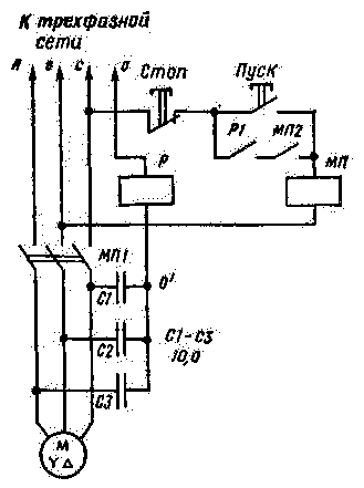
The second way (Fig. 3). The protective device is based on the principle of creating an artificial zero point (point D) formed by three identical capacitors C1-C3. Between this point and the neutral wire O, an additional relay P with normally closed contacts is connected. During normal operation of the electric motor, the voltage at point 0' is zero and no current flows through the relay winding. When one of the linear wires of the network is disconnected, the electrical symmetry of the three-phase system is violated, voltage appears at point 0 ', relay P is activated and contacts P1 de-energizes the magnetic starter winding - the engine is turned off. This device provides higher reliability than the previous one. Relay type MKU, for an operating voltage of 36 V. Capacitors C1-C3 - paper, with a capacity of 4-10 microfarads, for an operating voltage of at least twice the phase.
The sensitivity of the device is so high that sometimes the motor can turn off as a result of an electrical symmetry violation caused by the connection of extraneous single-phase consumers powered by this network. Sensitivity can be reduced by using capacitors with a smaller capacitance. The third way (Fig. 4). The scheme of the protective device is similar to the scheme considered in the first method. When the "Start" button is pressed, the relay P is turned on, with the contacts P1 closing the power supply circuit of the coil of the MP magnetic starter.
The magnetic starter is triggered and the MP1 contacts turn on the electric motor. In the event of a break in the line wires B or C, the relay R is switched off, in the event of a break in the wire L or C, the MP magnetic starter is switched off. In both cases, the electric motor is turned off by the contacts of the MP1 magnetic starter. Compared with the three-phase motor protective device circuit considered in the first method, this device has an advantage: the additional relay P is de-energized when the motor is turned off. References:
Publication: N. Bolshakov, rf.atnn.ru
Machine for thinning flowers in gardens
02.05.2024 Advanced Infrared Microscope
02.05.2024 Air trap for insects
01.05.2024
▪ Dual Channel Isolated SiC MOSFET Drivers 2EDF0275F and 2EDS9265H ▪ Gastronomic preferences of cats ▪ Solar-powered desalination plant ▪ Computer mouse without borders
▪ section of the site Radio - for beginners. Article selection ▪ Vintica's article. Popular expression ▪ article Where do spiders live that can move like acrobats performing somersaults? Detailed answer ▪ article Kopechnik arctic. Legends, cultivation, methods of application ▪ article The riddle of the torn poster. Focus Secret
Home page | Library | Articles | Website map | Site Reviews
www.diagram.com.ua |


 Leave your comment on this article: