|
|


 Arabic
 Bengali
 Chinese
 English
 French
 German
 Hebrew
 Hindi
Hindi Italian
 Japanese
 Korean
 Malay
Malay Polish
 Portuguese
 Spanish
 Turkish
 Ukrainian
 Vietnamese
|
Lecture notes, cheat sheets
General electronics and electrical engineering. Cheat sheet: briefly, the most important
Directory / Lecture notes, cheat sheets Table of contents
1. HISTORY OF ELECTRONICS The foundation for the emergence and development of electronics was laid by the work of physicists in the XNUMXth and XNUMXth centuries. The world's first studies of electrical discharges in air were carried out in the XNUMXth century. in Russia by academicians Lomonosov и Richmann and independently of them, American scientists Franklin. An important event was the discovery of the electric arc by Academician Petrov in 1802. Studies of the processes of the passage of electric current in rarefied gases were carried out in the last century in England Crooks, Thomson, Townsend, Aston, in Germany Geisler, Gittorf, Plücker and others. In 1873 Lodygin invented the world's first electric vacuum device - an incandescent lamp. Regardless of him, a little later, the same lamp was created and improved by an American inventor Edison. The electric arc was first used for lighting purposes Yablochkov in 1876. In 1887, a German physicist Hertz discovered the photoelectric effect. Thermionic emission was discovered in 1884 by Edison. In 1901, Richardson carried out a detailed study of thermionic emission. The first cold cathode cathode ray tube was built in 1897. Brown (Germany). The use of electronic devices in radio engineering began with the fact that in 1904 the English scientist Fleming used a two-electrode lamp with an incandescent cathode to rectify high-frequency oscillations in a radio receiver. In 1907 an American engineer Lee de Forest introduced a grid into the control lamp, i.e. created the first triode. In the same year, professor at the St. Petersburg Institute of Technology Rising proposed to use a cathode ray tube for receiving television images and in subsequent years carried out experimental confirmation of his ideas. In 1909-191 in Russia Kovalenkov created the first triodes to amplify long-distance telephone communications. The invention of the heated cathode was of great importance. Chernyshev in 1921. In 1926, Hell in the USA improved lamps with a shielding grid, and in 1930 he proposed a pentode, which became one of the most common lamps. In 1930 Kubecki invented photomultipliers, in the design of which Vekshinskiy and Timofeev made a significant contribution. The first proposal for special television transmission tubes was made independently in 1930-1931. Konstantinov and Kataev. Similar tubes, called iconoscopes, were built in the USA Zworykin. The invention of such tubes opened up new opportunities for the development of television. Somewhat later in 1933. Shmakov и Timofeev proposed new, more sensitive transmitting tubes (supericonoscopes or superemitters), which made it possible to conduct television transmissions without strong artificial lighting. Russian radiophysicist Rozhanovsky in 1932 he proposed to create new devices with speed modulation of the electron flow. According to his ideas, Arsen'eva and Heil in 1939 built the first such devices for amplifying and generating microwave oscillations, called transient klystrons. In 1940 Kovalenko invented a simpler reflective klystron, which is widely used to generate microwave oscillations. Of great importance for the technique of decimeter waves were the works Devyatkova, Daniltseva, Khokhlova и Gurevich, which in 1938-1941. designed special triodes with flat disk electrodes. According to this principle, cermet lamps were produced in Germany and beacon lamps in the USA. 2. SEMICONDUCTOR DEVICES Compared to vacuum tubes, semiconductor devices have significant advantages: 1) light weight and small size; 2) no energy consumption for heating; 3) higher reliability in operation and long service life (up to tens of thousands of hours); 4) high mechanical strength (resistance to shaking, shock and other types of mechanical overload); 5) various devices (rectifiers, amplifiers, generators) with semiconductor devices have a high efficiency, since energy losses in the devices themselves are insignificant; 6) low-power devices with transistors can operate at very low supply voltages; 7) the principles of the design and operation of semiconductor devices are used to create a new important direction in the development of electronics - semiconductor microelectronics. At the same time, semiconductor devices currently have the following disadvantages: 1) the parameters and characteristics of individual instances of devices of this type have a significant spread; 2) properties and parameters of devices strongly depend on temperature; 3) there is a change in the properties of devices over time (aging); 4) their own noise in some cases is greater than that of electronic devices; 5) most types of transistors are unsuitable for operation at frequencies above tens of megahertz; 6) the input resistance of most transistors is much less than that of vacuum tubes; 7) transistors are not yet manufactured for such high powers as electrovacuum devices; 8) the operation of most semiconductor devices deteriorates sharply under the influence of radioactive radiation. Transistors are successfully used in amplifiers, receivers, transmitters, generators, televisions, measuring instruments, pulse circuits, electronic calculating machines, etc. The use of semiconductor devices gives huge savings in the consumption of electrical energy from power sources and makes it possible to reduce the size of the equipment many times over. Research is underway to improve semiconductor devices by using new materials for them. Semiconductor rectifiers for currents of thousands of amperes have been created. The use of silicon instead of germanium makes it possible to operate devices at temperatures up to 125 "C and higher. Transistors have been created for frequencies up to hundreds of megahertz and more, as well as new types of semiconductor devices for microwave frequencies. The replacement of electron tubes with semiconductor devices has been successfully carried out in many radio engineering devices. The industry produces a large number of semiconductor diodes and transistors of various types. 3. MOTION OF ELECTRONS IN A HOMOGENEOUS ELECTRIC FIELD The interaction of electrons with an electric field is the main process in electrovacuum and semiconductor devices. An electron is a particle of matter with a negative electric charge, whose absolute value is e = 1,610-19C. The mass of an immobile electron is equal to m = 9,110-28g. As the speed of movement increases, the mass of electrons increases. theoretically, at a speed equal to c = 3·108m/s, the mass of an electron should become infinitely large. In conventional electrovacuum devices, the speed of electrons does not exceed 0,1 s. Under this condition, the mass of the electron can be considered constant, equal to m. If the potential difference between the electrodes is U, and the distance between them is d, then the field strength is: E \uXNUMXd U / d. For a uniform electric field, the value of E is constant. Let an electron with a kinetic energy W0 and an initial velocity v0 directed along the field lines be emitted from an electrode having a lower potential, for example, from a cathode. The field acts on an electron and accelerates its movement to an electrode with a higher potential, such as an anode. That is, the electron is attracted to the electrode with a higher potential. In this case, the field is called accelerating. In an accelerating field, an increase in the kinetic energy of an electron occurs due to the work of the field in moving the electron. In accordance with the law of conservation of energy, an increase in the kinetic energy of an electron W-W0 is equal to the work of the field, which is determined by the product of the transferred charge e and the potential difference U passed by it: WW! = mv2/2 - mv20/2 = eU. If the initial electron velocity is equal to zero, then W0 = mv20/2 = 0 and W=mv2/2 = eU, i.e. the kinetic energy of the electron is equal to the field work. The speed of an electron in an accelerating field depends on the potential difference passed through. Let the direction of the initial velocity of the electron v0 be opposite to the force F acting on the electron from the side of the field, i.e., the electron flies out with a certain initial velocity from the electrode with a higher potential. Since the force F is directed towards the velocity v0, the electron is decelerated and moves in a straight line, uniformly slow. The field in this case is called retarding. Therefore, this field for some electrons is accelerating, and for others - decelerating, depending on the direction of the initial electron velocity. In a decelerating field, an electron gives off energy to the field. In the opposite direction, the electron moves without initial speed in the accelerating field, which returns to the electron the energy lost by it during slow motion. If an electron flies in with an initial velocity v0 at right angles to the direction of the field lines, then the field acts on the electron with a force F determined by the formula f = eE and directed towards a higher potential. In the absence of force, the Rpotential would make a uniform motion by inertia with a speed v0. And under the action of the force F, the electron must move with uniform acceleration in the direction perpendicular to v0. The resulting motion of the electron occurs along a parabola, with the electron deflected towards the positive electrode. If the electron does not hit this electrode and goes beyond the field, then it will continue to move by inertia in a straight line and uniformly. An electron moves along a certain parabola, and either hits one of the electrodes, or leaves the field. An electric field always changes the kinetic energy and speed of an electron in one direction or another. Thus, there is always an energy interaction between an electron and an electric field, i.e., an energy exchange. If the initial velocity of the electron is not directed along the lines of force, but at some angle to them, then the electric field also bends the trajectory of the electron. 4. MOTION OF ELECTRONS IN A NONHOMOGENEOUS ELECTRIC FIELD For inhomogeneous electric fields characterized by a varied and often complex structure. There are many inhomogeneous fields that are not similar to each other, in which the intensity varies from point to point according to various laws, and the lines of force are usually curves of one form or another. The simplest is the radical inhomogeneous field often encountered in electrovacuum devices, which is formed between cylindrical electrodes. If the initial velocity of an electron emitted from the surface of the inner electrode is directed along the lines of force, then the electron will move in a straight line and accelerated along the radius. But as you move away from the inner electrode, the field strength and the force acting on the electron become smaller, which means that the acceleration also decreases. In a more general case, an inhomogeneous field has lines of force in the form of curved lines. If this field is accelerating, then the electron with the initial velocity v0 moves along a curvilinear trajectory that has the same curvature as the lines of force. The force F acts on the electron from the side of the field, directed at an angle to the electron's own velocity vector. This force bends the trajectory of the electron and increases its speed. In this case, the electron trajectory does not coincide with the field line. If the electron had no mass, and therefore no inertia, then it would move along the line of force. However, the electron has mass and tends to move by inertia in a straight line with the speed acquired during the previous movement. The force acting on the electron is directed tangentially to the field line and, in the case of curved field lines, forms an angle with the electron velocity vector. Therefore, the trajectory of the electron is curved, but "lags behind" in this curvature from the line of force due to the inertia of the electron. In the case of a decelerating inhomogeneous field with curved field lines, the force acting on the electron from the field also bends the electron trajectory and changes its velocity. But the curvature of the trajectory is obtained in the direction opposite to that to which the lines of force are bent, i.e., the trajectory of the electron tends to move away from the line of force. In this case, the speed of the electron decreases, as it passes to points with a more negative potential. Let us consider the motion of an electron flow in an inhomogeneous field, neglecting, for simplicity, the interaction of electrons. Let the electron flow move in an accelerating inhomogeneous field, which is symmetrical with respect to the average straight line of force. In this case, the lines of force converge in the direction of electron motion, i.e., the field strength increases. Let us call such a field converging. Let a stream of electrons fly into this field, the velocities of which are directed in parallel. The trajectories of electrons are bent in the same direction as the lines of force are bent. And only the average electron moves rectilinearly along the average line of force. As a result, the electrons approach each other, i.e., the focusing of the electron flow is obtained, resembling the focusing of the light flux with the help of a converging lens. In addition, the speed of the electrons increases. If the lines of force diverge in the direction of electron motion, then the field can be conventionally called divergent. In it, the electron flow is scattered, since the trajectories of electrons move away from each other during curvature. Therefore, the accelerating divergent field is a diverging lens for the electron beam. If the field is decelerating and converging, then there is no focusing, but scattering of electrons with a decrease in their speed. And vice versa, in a decelerating divergent field, the focusing of the electron beam is obtained. 5. MOTION OF ELECTRONS IN A UNIFORM MAGNETIC FIELD Some electrovacuum devices use the movement of electrons in a magnetic field. Let us consider the case when an electron flies into a uniform magnetic field with an initial velocity v0 directed perpendicular to the magnetic field lines. In this case, the moving electron is affected by the so-called Lorentz force F, which is perpendicular to the vector h0 and the vector of the magnetic field H. The magnitude of the force F is determined by the expression: F = ev0H. At v0 = 0, the force P is equal to zero, i.e., the magnetic field does not act on a stationary electron. The force F bends the electron trajectory into a circular arc. Since the force F acts at right angles to the speed h0, it does no work. The energy of an electron and its speed do not change in magnitude. There is only a change in the direction of speed. It is known that the motion of a body in a circle (rotation) at a constant speed is obtained due to the action of a centripetal force directed towards the center, which is precisely the force F. The direction of rotation of an electron in a magnetic field in accordance with the left-hand rule is conveniently determined by the following rules. Looking in the direction of the magnetic field lines, the electron moves clockwise. In other words, the rotation of the electron coincides with the rotational movement of the screw, which is screwed in the direction of the magnetic field lines. Let us determine the radius r of the circle described by the electron. To do this, we use the expression for the centripetal force known from mechanics: F = mv20/r. Let us equate it to the value of the force F = ev0H: mv20/r = ev0H. Now from this equation you can find the radius: r= mv0/(eH). The greater the electron velocity v0, the stronger it tends to move rectilinearly by inertia, and the radius of curvature of the trajectory will be larger. On the other hand, with increasing H, the force F increases, the curvature of the trajectory increases, and the radius of the circle decreases. The derived formula is valid for the motion of particles with any mass and charge in a magnetic field. Consider the dependence of r on m and e. A charged particle with a larger mass m tends to fly more rectilinearly by inertia and the curvature of the trajectory will decrease, i.e., will become larger. And the greater the charge e, the greater the force F and the more the trajectory is curved, i.e., its radius becomes smaller. Having gone beyond the magnetic field, the electron flies further by inertia in a straight line. If the radius of the trajectory is small, then the electron can describe closed circles in a magnetic field. Thus, the magnetic field only changes the direction of the electron velocity, but not its magnitude, i.e., there is no energy interaction between the electron and the magnetic field. Compared to an electric field, the effect of a magnetic field on electrons is more limited. That is why a magnetic field is used to influence electrons much less frequently than an electric field. 6. ELECTRONS IN SOLID STATES Modern physics has proved that electrons in a body cannot have arbitrary energies. The energy of each electron can only take on certain values, called energy levels (or energy levels). Electrons located closer to the nucleus of an atom have lower energies, that is, they are at lower energy levels. To remove an electron from the nucleus, it is necessary to overcome the mutual attraction between the electron and the nucleus. This requires some energy. Therefore, electrons far from the nucleus have high energies; they are at higher energy levels. When an electron moves from a higher energy level to a lower one, a certain amount of energy is released, called a quantum (or photon). If an atom absorbs one quantum of energy, then the electron moves from a lower energy level to a higher one. Thus, the energy of electrons changes only in quanta, that is, in certain portions. The distribution of electrons by energy levels is shown schematically: the energy W of the electron is plotted vertically, and the energy levels are shown by horizontal lines. In accordance with the so-called solid state zone theory, energy levels are combined into separate zones. The electrons of the outer shell of the atom fill a number of energy levels that make up the valence band. Lower energy levels are part of other bands filled with electrons, but these bands do not play a role in the phenomena of electrical conductivity and therefore they are not shown in the figure. In metals and semiconductors, there are a large number of electrons located on I higher energy levels. These levels make up the conduction band. The electrons of this zone, called conduction electrons, move randomly inside the body, moving from one atom to another. It is the conduction electrons that provide the high electrical conductivity of metals. Atoms of a substance that donated electrons to the conduction band can be considered as positive ions. They are arranged in a certain order, forming a spatial lattice, otherwise called ionic, or crystalline. The state of this lattice corresponds to the equilibrium of the forces of interaction between atoms and the minimum value of the total energy of all particles of the body. Random movement of conduction electrons occurs inside the spatial lattice. A different energy structure is characteristic of dielectrics. They have a band gap between the conduction band and the valence band, corresponding to energy levels at which electrons cannot be. At normal temperature, dielectrics have only a very small number of electrons in the conduction band, and therefore the dielectric has negligible conductivity. But when heated, some electrons of the valence band, receiving additional energy, pass into the conduction band, and then the dielectric acquires a noticeable electrical conductivity. Semiconductors at low temperatures are insulators, and at normal temperature a significant number of electrons pass from the valence band to the conduction band. At present, germanium and silicon, which have a valence of 4, are most widely used for the manufacture of semiconductor devices. The spatial crystal lattice of germanium or silicon consists of atoms bonded to each other by valence electrons. Such a bond is called covalent or pair-electron. 7. OWN ELECTRON AND HOLE ELECTRICAL CONDUCTIVITY Semiconductors are substances that, in terms of electrical conductivity, occupy a middle position between conductors and dielectrics. For semiconductors characterized by a negative temperature coefficient of electrical resistance. As temperature rises, the resistance of semiconductors decreases rather than increases as with most solid conductors. In addition, the electrical resistance of semiconductors depends very much on the amount of impurities, as well as on such external influences as light, electric field, ionizing radiation, etc. There are two types of electrical conductivity in semiconductors. Like metals, semiconductors have electronic electrical conductivity, which is due to the movement of conduction electrons. At ordinary operating temperatures, semiconductors always contain conduction electrons, which are very weakly bound to the nuclei of atoms and perform random thermal movement between the atoms of the crystal lattice. These electrons, under the action of a potential difference, can receive additional movement in a certain direction, which is an electric current. Semiconductors also have hole electrical conductivity, which is not observed in metals. In semiconductors, the crystal lattice is quite strong. Its ions, i.e., atoms deprived of one electron, do not move, but remain in their places. The absence of an electron in an atom is conventionally called hole. This emphasizes that one electron is missing in the atom, i.e., a free space has formed. Holes behave like elementary positive charges. With hole electrical conductivity, electrons actually move too, but to a more limited extent than with electronic electrical conductivity. Electrons pass from these atoms only to neighboring ones. The result of this is the movement of positive charges - holes - in the opposite direction to the movement of electrons. Electrons and holes that can move around and therefore create electrical conductivity are called mobile charge carriers or simply charge carriers. It is customary to say that under the action of heat, pairs of charge carriers are generated, i.e., pairs arise: a conduction electron - a conduction hole. Due to the fact that the conduction electrons and holes perform a chaotic thermal motion, the reverse process of the generation of carrier pairs necessarily occurs. Conduction electrons again occupy free places in the valence band, i.e., they combine with holes. This disappearance of pairs of carriers is called recombination of charge carriers. The processes of generation and recombination of pairs of carriers always occur simultaneously. A semiconductor without impurities is called an intrinsic semiconductor. It has its own electrical conductivity, which consists of electronic and hole electrical conductivity. In this case, despite the fact that the number of electrons and holes of conduction in the intrinsic semiconductor is the same, the electronic electrical conductivity prevails, which is explained by the greater mobility of electrons compared to the mobility of holes. 8. IMPURITY ELECTRICAL CONDUCTIVITY If the semiconductor contains impurities of other substances, then in addition to the intrinsic electrical conductivity, an impurity electrical conductivity also appears, which, depending on the type of impurity, can be electronic or hole. For example, germanium, being tetravalent, has impurity electronic conductivity if pentavalent antimony and arsenic are added to it. Their atoms interact with germanium atoms with only four of their electrons, and the fifth electron is given to the conduction band. As a result, a certain amount of additional conduction electrons is obtained. Impurities in which atoms donate electrons are called donors. Donor atoms lose electrons and become positively charged. Semiconductors with a predominance of electronic electrical conductivity are called electronic semiconductors or n-type semiconductors. Substances that take electrons and create impurity hole electrical conductivity are called acceptors. Acceptor atoms, capturing electrons, themselves become negatively charged. Semiconductors with a predominance of hole electrical conductivity are called hole semiconductors or p-type semiconductors. Semiconductor devices mainly use semiconductors containing donor or acceptor impurities and are called impurity. At normal operating temperatures in such semiconductors, all impurity atoms participate in the creation of impurity electrical conductivity, i.e., each impurity atom either donates or captures one electron. In order for the impurity electrical conductivity to prevail over the intrinsic one, the concentration of donor impurity or acceptor impurity atoms must exceed the concentration of intrinsic charge carriers. Charge carriers, the concentration of which in a given semiconductor prevails, are called the main ones. They are electrons in an n-type semiconductor and holes in a p-type semiconductor. The minority charge carriers are called, the concentration of which is less than the concentration of the majority carriers. The concentration of minority carriers in an impurity semiconductor decreases as many times as the concentration of majority carriers increases. If there was a certain number of electrons in germanium, and after the addition of a donor impurity, the electron concentration increased by a factor of 1000, then the concentration of minority carriers (holes) will decrease by a factor of 1000, i.e., it will be a million times less than the concentration of major carriers. This is explained by the fact that with a 1000-fold increase in the concentration of conduction electrons obtained from donor atoms, the lower energy levels of the conduction band turn out to be occupied and the transition of electrons from the valence band is possible only to higher levels of the conduction band. But for such a transition, the electrons must have a high energy, and therefore a much smaller number of electrons can carry it out. Correspondingly, the number of conduction holes in the valence band decreases significantly. Thus, a negligibly small amount of impurity significantly changes the nature of the electrical conductivity and the magnitude of the conductivity of the semiconductor. Obtaining semiconductors with such a low and strictly dosed content of the desired impurity is a very complex process. In this case, the initial semiconductor to which the impurity is added must be very pure. 9. DIFFUSION OF CHARGE CARRIERS IN SEMICONDUCTORS In semiconductors, in addition to the conduction current, there may also be a diffusion current, the cause of which is not the potential difference, but the difference in carrier concentrations. Let us find out the essence of this current. If the concentration of charge carriers is distributed uniformly over the semiconductor, then it is equilibrium. Under the influence of any external influences in different parts of the semiconductor, the concentration may become unequal, i.e., non-equilibrium. For example, if a part of a semiconductor is exposed to radiation, then the process of generating pairs of carriers will intensify in it and an additional concentration of carriers will appear, called redundant. Since carriers have their own kinetic energy, they always tend to move from places with a higher concentration to places with a lower concentration, i.e. e. tend to equalize the concentration. The phenomenon of diffusion is observed for many particles of matter, and not only for mobile charge carriers. Diffusion is always caused by the uneven concentration of particles, and diffusion itself is carried out due to the self-energy of the thermal motion of particles. The diffuse motion of mobile charge carriers (electrons and holes) is a diffuse current /. This current, like the conduction current, can be electron or hole. The densities of these currents are determined by the following formulas: i = eDn ?n /?x and ip=- eDp?p /?x, where the values ?n/?x and ?c/?x are the so-called concentration gradients, and Dn and Dp are coefficients diffusion. The concentration gradient characterizes how sharply the concentration changes along the distance x, i.e., what is the change in concentration n or p per unit length. If there is no concentration difference, then ?n=0 or ?p =0 and no diffusion current occurs. And the greater the change in concentration ?n or ?p at a given distance ?x, the greater the diffusion current. The diffusion coefficient characterizes the intensity of the diffusion process. It is proportional to the mobility of carriers, different for different substances, and depends on temperature. The diffusion coefficient for electrons is always greater than for holes. The minus sign on the right side of the formula for the hole diffusion current density is set because the hole current is directed in the direction of decreasing hole concentration. If, due to some external influence, an excess concentration of carriers is created in some part of the semiconductor, and then the external influence stops, then the excess carriers will recombine and propagate by diffusion to other parts of the semiconductor. The value that characterizes the process of decreasing the excess concentration with time is called the lifetime of nonequilibrium carriers. The recombination of nonequilibrium carriers occurs in the bulk of the semiconductor and on its surface and strongly depends on impurities, as well as on the state of the surface. During diffuse propagation of nonequilibrium carriers, such as electrons, along a semiconductor, their concentration also decreases with distance due to recombination. 10. ELECTRON-HOLE JOINT IN THE ABSENCE OF EXTERNAL VOLTAGE The region at the boundary of two semiconductors with different types of electrical conductivity is called electron-hole, or p-p-transition. An electron-hole transition has the property of asymmetric conductivity, i.e., it has a non-linear resistance. The operation of most semiconductor devices used in radio electronics is based on the use of the properties of one or more pn junctions. Let us consider the physical processes in such a transition. Let there be no external voltage across the junction. Since charge carriers in each semiconductor perform random thermal motion, i.e., they have their own velocities, their diffusion (penetration) from one semiconductor to another occurs. Carriers move from where their concentration is high to where the concentration is low. Thus, electrons diffuse from an n-type semiconductor into a p-type semiconductor, and holes diffuse from a p-type semiconductor into an n-type semiconductor in the opposite direction. As a result of diffusion of carriers, space charges of different signs are created on both sides of the interface between two semiconductors with different types of electrical conductivity. In the n region, a positive space charge arises. It is formed mainly by positively charged donor impurity atoms and, to a small extent, by holes that have entered this region. Similarly, a negative space charge arises in the region p, formed by the negatively charged atoms of the acceptor impurity and partly by the electrons that have arrived here. Between the formed space charges there is a so-called contact potential difference and an electric field. A potential barrier arises in the p-n junction, which prevents the diffusion transition of carriers. The higher the concentration of impurities, the higher the concentration of the main carriers and the greater the amount of them diffuse through the boundary. The density of space charges increases and the contact potential difference increases, i.e., the height of the potential barrier. In this case, the thickness of the pn junction decreases. Simultaneously with the diffuse movement of the majority carriers across the boundary, the reverse movement of the carriers occurs under the action of the electric field of the contact potential difference. This field moves holes from the p-region back to the p-region and electrons from the p-region back to the p-region. At a certain temperature, the pn junction is in a state of dynamic equilibrium. Every second, a certain number of electrons and holes diffuse through the boundary in opposite directions, and under the action of the field, the same number of them drift in the opposite direction. The movement of carriers due to diffusion is a diffusion current, and the movement of carriers under the action of a field is a conduction current. At the dynamic equilibrium of the transition, these currents are equal and opposite in direction. Therefore, the total current through the junction is zero, which should be the case in the absence of an external voltage. Each of the currents has an electron and a hole component. The values of these components are different, since they depend on the concentration and mobility of the carriers. The height of the potential barrier is always automatically set exactly to the point at which equilibrium occurs, i.e., the diffusion current and the conduction current mutually compensate each other. 11. ELECTRON-HOLE TRANSITION UNDER THE ACTION OF A FORWARD VOLTAGE Let the external voltage source be connected with a positive pole to a p-type semiconductor, and with a negative pole to an n-type semiconductor. The electric field created in the pn junction by direct voltage acts towards the field of the contact potential difference. The resulting field becomes weaker and the potential difference in the junction decreases, i.e., the height of the potential barrier decreases, and the diffusion current increases. After all, a lower barrier can overcome a greater number of carriers. The conduction current almost does not change, since it depends mainly only on the number of minority carriers that, due to their thermal velocities, enter the region of the p-n junction from the volumes of the n- and p-regions. In the absence of an external voltage, the diffuse current and the conduction current are equal and mutually compensate each other. With a forward voltage, idif> iprov, and therefore the total current through the junction, i.e., direct current, is no longer equal to zero: ipr \u0d idif - iprov> XNUMX. If the barrier is significantly lowered, then idiff "iprov and we can assume that ipr ~ idif, i.e., the forward current in the junction is diffusion. The phenomenon of the introduction of charge carriers through a lowered potential barrier into a region where these carriers are minor is called injection of charge carriers. The region of a semiconductor device from which carriers are injected is called the emitter region, or emitter. And the region into which charge carriers that are minor for this region are injected is called the base region, or base. Thus, if we consider the injection of electrons, then the p-region is the emitter, and the p-region is the base. For hole injection, on the contrary, the p-region serves as the emitter, and the p-region is the base. In semiconductor devices, the concentration of impurities, and hence the majority carriers, in the n- and p-regions is usually very different. Therefore, the injection from the region with a higher concentration of the main carriers strongly dominates. Accordingly, this predominant injection gives the name emitter and base. For example, if pp "pp, then the injection of electrons from the n-region into the p-region is much greater than the injection of holes in the opposite direction. In this case, the n-region is considered the emitter, and the p-region is considered the base, since hole injection can be neglected. With a forward voltage, not only the potential barrier decreases, but the thickness of the barrier layer also decreases. This leads to a decrease in the resistance of the barrier layer. Its resistance in the forward direction is small. Since the height of the barrier in the absence of an external voltage is several tenths of a volt, to significantly lower the barrier and significantly reduce the resistance of the blocking layer, it is sufficient to apply a forward voltage to the p-n junction of only tenths of a volt. Therefore, a significant forward current can be obtained with a very small forward voltage. Obviously, at a certain forward voltage, it is possible to completely destroy the potential barrier in the pn junction. Then the resistance of the transition, i.e., the barrier layer, will become close to zero and can be neglected. The forward current in this case will increase and will depend on the resistance of the volumes of the pi p regions. Now these resistances cannot be neglected, since it is they who remain in the circuit and determine the magnitude of the current. 12. ELECTRON-HOLE JUNCTION AT REVERSE VOLTAGE Let the source of external voltage be connected with a positive pole to the region n, and a negative one - to the region p. Under the influence of such a reverse voltage, a very small reverse current flows through the passage, which is explained as follows. The field created by the reverse voltage is added to the field of the contact potential difference. The resulting field is amplified. Already at a slight increase in the barrier, the diffusion movement of the majority carriers through the junction stops, since the intrinsic velocities of the carriers are insufficient to overcome the barrier. And the conduction current remains almost unchanged, since it is determined mainly by the number of minority carriers that enter the p-n junction region from the volumes of the n- and p-regions. The removal of minority carriers through a pn junction by an accelerating electric field created by an external voltage is called extraction of charge carriers. Thus, the reverse current is practically a conduction current formed by the movement of minority carriers. The reverse current turns out to be very small, since there are few minority carriers and, in addition, the resistance of the barrier layer with a reverse voltage is very high. Indeed, as the reverse voltage increases, the field in the transition region becomes stronger, and under the action of this field, more majority carriers are `pushed out' from the boundary layers into the depths of the pyrp regions. Therefore, with an increase in the reverse voltage, not only the height of the potential barrier increases, but also the thickness of the barrier layer. This layer becomes even more depleted of carriers, and its resistance increases significantly. Even with a relatively small reverse voltage, the reverse current reaches an almost constant value, which can be called the saturation current. This is because the number of minority carriers is limited. With increasing temperature, their concentration increases and the reverse current increases, and the reverse resistance decreases. Let us consider in more detail how the reverse current is set when the reverse voltage is turned on. First, there is a transient process associated with the movement of the main carriers. Electrons in the p-region move towards the positive pole of the source, i.e., they move away from the p-p-transition. And in the p-region, moving away from the p-n junction, holes move. At the negative electrode, they recombine with electrons that come from the wire connecting this electrode to the negative pole of the source. Since electrons leave the n-region, it becomes positively charged, since positively charged atoms of the donor impurity remain in it. Similarly, the p region becomes negatively charged, its holes are filled with incoming electrons, and negatively charged acceptor impurity atoms remain in it. The considered movement of the main carriers in opposite directions lasts only a small period of time. This transient current is similar to the charging current of a capacitor. On both sides of the p-n junction, two opposite space charges arise, and the whole system becomes similar to a charged capacitor with a bad dielectric, in which there is a leakage current (its role is played by the reverse current). But the leakage current of the capacitor, in accordance with Ohm's law, is proportional to the applied voltage, and the reverse current of the p-n junction depends relatively little on the voltage. 13. VOLT-AMPERE CHARACTERISTICS OF A SEMICONDUCTOR DIODE For any electrical device, the relationship between the current through the device and the applied voltage is important. Knowing this dependence, it is possible to determine the current at a given voltage or, conversely, the voltage corresponding to a given current. If the resistance of the device is constant, independent of current or voltage, it is expressed by Ohm's law: i= u/R, or i= Gu. Current is directly proportional to voltage. The coefficient of proportionality is the conductivity G =1/R. The graph of the relationship between current and voltage is called the "voltage characteristic" of this device. For a device that obeys Ohm's law, the characteristic is a straight line passing through the origin. Devices that obey Ohm's law and have a current-voltage characteristic in the form of a straight line passing through the origin are called linear. There are also devices in which the resistance is not constant, but depends on voltage or current. For such devices, the relationship between current and voltage is not expressed by Ohm's law, but in a more complex way, and the current-voltage characteristic is not a straight line. These devices are called non-linear. An electron-hole junction is essentially a semiconductor diode. The reverse current increases rapidly as the reverse voltage increases at first. This is due to the fact that already at a small reverse voltage, due to an increase in the potential barrier in the junction, the diffusion current sharply decreases, which is directed towards the conduction current. Consequently, the total current increases sharply. However, with a further increase in the reverse voltage, the current increases slightly, i.e., a phenomenon resembling saturation occurs. The increase in current occurs due to the heating of the junction by the current, due to leakage over the surface, and also due to the avalanche multiplication of charge carriers, i.e., an increase in the number of charge carriers as a result of impact ionization. This phenomenon consists in the fact that at a higher reverse voltage, the electrons acquire a greater speed and, hitting the atoms of the crystal lattice, knock out new electrons from them, which in turn are accelerated by the field and also knock out electrons from the atoms. This process intensifies with increasing voltage. At a certain value of the reverse voltage, breakdown pn-junction, in which the reverse current increases sharply and the resistance of the barrier layer decreases sharply. It is necessary to distinguish between electrical and thermal breakdown of the pn-junction. An electrical breakdown is reversible if, during this breakdown, no irreversible changes (destruction of the substance structure) occur in the junction. Therefore, the operation of the diode in the mode of electrical breakdown is permissible. There may be two types of electrical breakdown, which often accompany each other: avalanche и tunnel. The avalanche breakdown is explained by the considered carrier avalanche multiplication due to impact ionization. This breakdown is typical for pn-junctions of great thickness, obtained at a relatively low concentration of impurities in semiconductors. The breakdown voltage for avalanche breakdown is typically tens or hundreds of volts. Tunneling breakdown is explained by a very interesting phenomenon of the tunneling effect. Its essence lies in the fact that with a sufficiently strong field with a strength of more than 105 V / cm, acting in a p-g junction of small thickness, some electrons penetrate through the junction without changing their energy. Thin transitions, in which the tunneling effect is possible, are obtained at a high impurity concentration. The breakdown voltage corresponding to tunnel breakdown usually does not exceed a few volts. 14. CAPACITY OF A SEMICONDUCTOR DIODE The P-n junction at reverse voltage is similar to a capacitor with significant leakage in the dielectric. The blocking layer has a very high resistance, and on both sides of it there are two opposite space charges created by ionized atoms of the donor and acceptor impurities. Therefore, the pn junction has a capacitance similar to that of a capacitor with two plates. This container is called barrier capacity. The barrier capacitance, like the capacitance of conventional capacitors, increases with an increase in the area of the pn-junction and the dielectric constant of the semiconductor substance and with a decrease in the thickness of the barrier layer. A feature of the barrier capacitance is that it is a non-linear capacitance, i.e., it changes with a change in the voltage at the junction. If the reverse voltage increases, then the thickness of the barrier layer increases. And since this layer plays the role of a dielectric, the barrier capacitance decreases. Barrier capacitance is detrimental to AC rectification because it shunts the diode and AC current flows through it at higher frequencies. But at the same time, there is also a useful application of the barrier capacitance. Special diodes called varicaps, used as variable capacitors for tuning oscillatory circuits, as well as in some circuits, the operation of which is based on the use of non-linear capacitance. Unlike conventional variable capacitors, in which the change in capacitance occurs mechanically, in varicaps this change is achieved by adjusting the magnitude of the reverse voltage. The method of tuning oscillatory circuits using varicaps is called electronic setting. With a forward voltage, the diode, in addition to the barrier capacitance, has the so-called diffusion capacitance, which is also nonlinear and increases with increasing forward voltage. Diffusion capacitance characterizes the accumulation of mobile charge carriers in the n- and p-regions in the presence of a forward voltage at the junction. It exists only at a forward voltage, when charge carriers diffuse in large quantities through a reduced potential barrier and, without having time to recombine, accumulate in the n- and p-regions. So, for example, if in some diode the p-region is an emitter, and the p-region is the base, then when a forward voltage is applied from the p-region to the p-region, a large number of holes rush through the junction and, therefore, a positive charge. At the same time, under the action of a direct voltage source, electrons enter the p-region from the wire of the external circuit, and a negative charge arises in this region. Holes and electrons in the n-region cannot instantly recombine. Therefore, each value of the forward voltage corresponds to a certain value of two equal opposite charges accumulated in the n-region due to the diffusion of carriers through the junction. The diffusion capacitance is much greater than the barrier capacitance, but in most cases it does not have a significant effect on the operation of the diode, and it cannot be used either, since it is always shunted by the low direct resistance of the diode itself. As a rule, only the barrier capacitance is of practical importance. 15. APPLICATION OF SEMICONDUCTOR DIODES FOR RECTIFICATION OF AC AC rectification is one of the main processes in radio electronics. In a rectifier, AC energy is converted into DC energy. Semiconductor diodes conduct current well in the forward direction and poorly conduct in the reverse direction, and, therefore, the main purpose of most diodes is AC rectification. In rectifiers, a power transformer connected to the electrical network usually serves as a variable emf generator to power electronic equipment. Instead of a transformer, an autotransformer is sometimes used. In some cases, the rectifier is powered by the transformer mains. The role of the load resistor, i.e., the consumer of direct current energy, in practical circuits is played by those circuits or devices that are powered by a rectifier. When rectifying high-frequency currents, for example, in the detector stages of radio receivers, a high-frequency transformer or a resonant oscillatory circuit serves as a variable EMF generator, and a specially included load resistor has a large resistance. The use of a capacitor doubles the reverse voltage compared to its value in the absence of a capacitor. A very dangerous is a short circuit of the load, which, in particular, occurs when the capacitor of the smoothing filter breaks down. Then the entire source voltage will be applied to the diode and the current will become unacceptable. going on thermal breakdown of the diode. The advantage of semiconductor diodes in comparison with vacuum ones is not only the absence of cathode heating, but also a small voltage drop across the diode with direct current. Regardless of the magnitude of the current, i.e., the power for which the semiconductor diode is designed, the forward voltage across it is tenths of a volt or a little more than 1 V. Therefore, the efficiency of rectifiers with semiconductor diodes is higher than with vacuum diodes. When rectifying higher voltages, the efficiency increases, since in this case a voltage loss of about 1V on the diode itself is not significant. Thus, semiconductor diodes are more economical than vacuum diodes and emit less heat during operation, which creates harmful heating of other parts located nearby. Also, semiconductor diodes have a very long service life. But their disadvantage is a relatively low limiting reverse voltage of no more than hundreds of volts, while for high-voltage kenotrons it can be up to tens of kilovolts. Semiconductor diodes can be used in any rectifier circuits. If the smoothing filter of the rectifier starts with a large capacitor, then when the AC voltage is turned on, a current pulse occurs to charge the capacitor, often exceeding the allowable forward current of this diode. Therefore, to reduce this current, sometimes a limiting resistor with a resistance of the order of units or tens of ohms is sometimes connected in series with the diode. In semiconductor diodes operating in rectifier mode, significant reverse current pulses can be observed when the voltage polarity is reversed. These impulses arise for two reasons. First, under the influence of the reverse voltage, a current pulse is obtained that charges the barrier capacitance of the pn junction. The larger this capacitance, the greater this momentum. Secondly, under reverse voltage, minority carriers accumulated in the n- and p-regions are dissipated. In practice, due to the difference in impurity concentrations in these regions, the main role is played by the larger charge accumulated in one of the regions. 16. GENERAL INFORMATION ABOUT TRANSISTORS Among the electrically converting semiconductor devices, i.e., devices used to convert electrical quantities, an important place is occupied by transistors. They are semiconductor devices suitable for power amplification and have three or more terminals. Transistors can have a different number of transitions between regions with different electrical conductivity. The most common transistors with two pn-transitions. These transistors are called bipolar, since their work is based on the use of charge carriers of both signs. The first transistors were point type, but they were not stable enough. Currently manufactured and used exclusively planar transistors. A planar bipolar transistor is a plate of germanium or another semiconductor in which three regions with different electrical conductivity are created. The middle region of the transistor is called the base, one extreme region is the emitter, the other is the collector. Thus, the transistor has two pn junctions - the emitter junction between the emitter and the base and the collector junction between the base and the collector. The distance between them should be very small, no more than a few microns, i.e., the base area should be very thin. This is the most important condition for the good operation of the transistor. In addition, usually the concentration of impurities in the base is much less than in the collector and emitter. With the help of metal electrodes from the base, emitter and collector, conclusions are drawn. ( A transistor can operate in three modes, depending on what the voltages are at its junctions. Operation in the active mode is obtained if the voltage is direct at the emitter junction, and reverse at the collector junction. The cut-off or blocking mode is achieved by applying a reverse voltage to both transitions. If the voltage is direct at both junctions, then the transistor operates in saturation mode. Active mode is the main one. In particular, it is used in most amplifiers and oscillators. In practical circuits with transistors, two circuits are usually formed. The input, or control, circuit is used to control the operation of the transistor. In the output, or controlled, circuit, enhanced oscillations are obtained. The source of amplified oscillations is included in the input circuit, and the load is included in the output circuit. Dependencies between currents and voltages in transistors are expressed by their static characteristics, i.e., characteristics taken at direct current and in the absence of load in the output circuit. The input and output characteristics of a transistor are closely related to the current-voltage characteristic of a semiconductor diode. The input specifications refer to an emitter junction that operates at forward voltage. Therefore, they are similar to the reverse current characteristic of a diode. The output characteristics are similar to the reverse current characteristic of a diode in that they reflect the properties of a collector junction operating at reverse voltage. There are also feedback characteristics that show how the voltage at the input of the transistor changes under the influence of a change in the output voltage, provided that the input current is constant. 17. PHYSICAL PROCESSES IN A TRANSISTOR Consider how the transistor works in static mode without load, when only sources of constant supply voltages are turned on. Their polarity is such that the voltage at the emitter junction is direct, and at the collector junction it is reversed. Therefore, the resistance of the emitter junction is small, and a source with a voltage of the order of tenths of a volt is sufficient to obtain a normal current in this junction. The resistance of the collector junction is high and the voltage is usually units or tens of volts. The principle of operation of the transistor is that the forward voltage of the emitter junction significantly affects the collector current: the higher the voltage, the greater the emitter and collector currents. In this case, the change in the collector current is only slightly less than the change in the emitter current. Thus, the input voltage controls the collector current. The amplification of electrical oscillations with the help of a transistor is based precisely on this phenomenon. Physical processes in the transistor occur as follows. With an increase in the direct input voltage, the potential barrier in the emitter junction decreases and, accordingly, the current through this junction increases - the emitter current. The electrons of this current are injected from the emitter into the base and, due to the phenomenon of diffusion, penetrate through the base into the region of the collector junction, increasing the collector current. Since the collector junction operates at a reverse voltage, space charges are obtained in the region of this junction. Between them there is an electric field. It promotes the passage of electrons that have come here from the emitter through the collector junction, i.e., it draws electrons into the region of the collector junction. If the base thickness is small enough and the concentration of holes in it is low, then the majority of electrons, having passed through the base, do not have time to recombine with the base holes and reach the collector junction. Only a small fraction of electrons recombine with holes in the base. As a result of this recombination, there is a base current flowing in the base wire. As a result of recombination, a certain number of holes disappear every second, but the same number of new holes appear every second due to the same number of electrons leaving the base towards the source pole. There can be no accumulation of any large number of electrons in the base. The base current is useless and even harmful. It is desirable that the base current be as small as possible. To do this, the base is made very thin and the concentration of impurities in it, which determines the concentration of holes, is reduced. Under these conditions, a smaller number of electrons will recombine in the base with holes. The name "emitter" given to one of the electrodes emphasizes that the electrons, as it were, emit from this electrode to the base. In fact, it is not emission, but the injection of electrons from the emitter into the base. The use of this term is necessary in order to distinguish this phenomenon from electron emission, which results in the production of electrons in a vacuum or rarefied gas. The emitter should be called the region of the transistor, the purpose of which is the injection of charge carriers into the base. A collector is an area whose purpose is to extract charge carriers from the base. And the base is the region into which charge carriers that are minor for this region are injected by the emitter. The emitter and collector can be interchanged. But in transistors, as a rule, the collector junction is made with a much larger area than the emitter junction, since the power dissipated in the collector junction is much greater than in the emitter junction. 18. BASIC SCHEMES OF TURNING ON TRANSISTORS Apply three main schemes inclusion of transistors in amplifying or other cascades. In these circuits, one of the transistor electrodes is the common entry and exit point of the stage. The basic circuits for switching transistors are called, respectively, circuits with a common emitter, a common base and a common collector. The common emitter circuit is the most common, as it gives the highest power gain. The current gain of such a stage is the ratio of the amplitudes of the output or input alternating currents, i.e., the variable components of the collector and base currents. Since the collector current is tens of times greater than the base current, the current gain is of the order of tens. The amplifying properties of a transistor when it is turned on according to a circuit with a common emitter is characterized by one of its main parameters - the static current gain for a circuit with a common emitter. Since it should characterize only the transistor itself, it is determined in the no-load mode, i.e., at a constant collector-emitter voltage. The voltage gain of the cascade is equal to the ratio of the amplitudes of the output and input alternating voltages. The input is the base-emitter voltage, and the output is the AC voltage across the load resistor or between the collector and emitter. The common-base circuit gives much less power gain and has even lower input impedance than the common-emitter circuit, yet it is used quite often, since it is much better than the common-emitter circuit in terms of its frequency and temperature properties. The current gain of a stage with a common base is always slightly less than unity. This follows from the fact that the collector current is always only slightly less than the emitter current. The most important parameter of transistors is the static current gain for a common base circuit. It is determined for the no-load mode, i.e., at a constant voltage "collector - base". For a common-base circuit, there is no phase shift between the output and input voltage, i.e., the phase of the voltage does not reverse during amplification. Scheme with a common collector. In it, indeed, the collector is a common entry and exit point, since the power supplies are always shunted with large capacitors and for AC can be considered a short circuit. The peculiarity of this circuit is that the input voltage is completely transferred back to the input, i.e. there is a very strong negative feedback. The input voltage is equal to the sum of the base-emitter AC voltage and the output voltage. The current gain of the cascade with a common collector is almost the same as in the circuit with a common emitter, i.e., it has a value of the order of tens. The voltage gain is close to unity, but always less than it. The output voltage is in phase with the input voltage and is almost equal to it in magnitude. That is, the output voltage repeats the input. 19. FREQUENCY PROPERTIES OF TRANSISTORS As the frequency increases, the gain provided by the transistors decreases. There are two main reasons for this phenomenon. First, at higher frequencies, it is detrimental to collector junction capacitance. At low frequencies, the capacitance resistance is very large, the collector resistance is also very large, and it can be considered that all the current goes to the load resistor. But at a certain high frequency, the resistance of the capacitance becomes relatively small and a noticeable part of the current created by the generator branches off into it, and the current in the resistor decreases accordingly. Consequently, the output voltage and output power are reduced. The capacitance of the emitter junction also reduces its resistance with increasing frequency, but it is always shunted by the low resistance of the emitter junction and therefore its harmful effect can only appear at very high frequencies. In practice, at lower frequencies, the capacitance, which is shunted by a very large collector junction resistance, is already so strongly affected that the operation of a transistor that could be affected by the capacitance becomes impractical. Therefore, the effect of capacitance in most cases can be ignored. The second reason for the decrease in gain at higher frequencies is AC phase lag collector from an alternating current emitter. It is caused by the inertia of the process of moving carriers through the base from the emitter junction to the collector junction, as well as by the inertia of the processes of charge accumulation and dissipation in the base. Carriers, such as electrons in an npn type transistor, perform diffusion motion in the base and therefore their speed is not very high. The transit time of carriers through the base in conventional transistors is on the order of 10-7 s, i.e. 0,1 μs or less. Of course, this time is very short, but at frequencies of the order of units and tens of megahertz and higher, it causes a noticeable phase shift between the collector and emitter currents. Due to this phase shift at high frequencies, the base alternating current increases, and this reduces the current gain. Let us denote the current gain for the circuit with a common emitter in, and the current gain for the circuit with a common base b. As the frequency increases, v decreases much more than b. The coefficient b decreases from the influence of the capacitance, and the value of c is also affected by the phase shift between the collector and emitter currents due to the time the carriers travel through the base. The common-emitter circuit, compared to the common-base circuit, has significantly worse frequency properties. It is customary to consider the maximum allowable decrease in the values of b and c by 30% compared to their values at low frequencies. Those frequencies at which such a decrease in gain is obtained are called the boundary, or limiting, gain frequencies for circuits with a common base and a common emitter. In addition to the limiting amplification frequencies, the transistor is also characterized by a maximum generation frequency, at which the cascade power gain decreases to 1. At high frequencies, not only the values \uXNUMXb\uXNUMXbof and c change. Due to the influence of junction capacitances and carrier transit time through the base, as well as the processes of accumulation and dissipation of charges in the base, the intrinsic parameters of the transistor at high frequencies change their value and are no longer purely active resistances. All other parameters also change. Higher cut-off frequencies can be obtained using semiconductors that have higher carrier mobility. 20. PULSE MODE OF TRANSISTORS Transistors, like semiconductor diodes, are used in various pulsed devices. The operation of transistors in a pulsed mode, otherwise called a key or switching mode, has a number of features. Consider pulse mode transistor using its output characteristics for a common-emitter circuit. Let a load resistor be included in the collector circuit. Usually, before the input of the transistor receives a pulse of input current or input voltage, the transistor is in the off state. A small current flows in the collector circuit, and, therefore, this circuit can be approximately considered open. The source voltage is almost all completely applied to the transistor. If a current pulse with a maximum value is applied to the input, then the transistor goes into the saturation region. It turns out a collector current pulse with a maximum value. It is sometimes referred to as saturation current. In this mode, the transistor acts as a closed key and almost all the source voltage drops across the resistor, and the transistor has only a very small residual voltage of the order of ten fractions of a volt, commonly called saturation voltage. If the input current pulse is less than the maximum value, then the collector current pulse will also decrease. But on the other hand, an increase in the base current pulse above the maximum value no longer gives an increase in the output current pulse. The pulsed mode is also characterized by the current gain, which, in contrast to v, is determined not through the increment of currents, but as the ratio of currents corresponding to the saturation mode. In other words, β is a parameter that characterizes the amplification of small signals, and the current gain refers to the amplification of large signals, in particular pulses, and differs somewhat from β in magnitude. The parameter of the pulse mode of the transistor is also its saturation resistance. The value of saturation resistance for transistors intended for pulse operation is usually on the order of units, sometimes tens of ohms. Similarly to the considered circuit with a common emitter, the circuit with a common base also operates in a pulsed mode. If the duration of the input pulse is many times longer than the time of transient processes of accumulation and dissipation of charges in the base of the transistor, then the output current pulse will have almost the same duration and shape as the input pulse. But with short pulses, a significant distortion of the output current pulse shape and an increase in its duration can be observed. The gradual increase in current is associated with the process of accumulation of carriers in the base. In addition, the carriers injected into the base at the beginning of the input current pulse have different rates of their diffusion motion and do not all reach the collector at once. After the end of the input pulse due to the process of dissipation of the charge accumulated in the base, the current continues for some time, and then gradually decreases during the decay time. Consequently, the process of switching on and off the collector circuit slows down, the time during which it is in a closed state is delayed. In other words, due to the inertia of the processes of accumulation and dissipation of the charge in the base, the transistor cannot carry out sufficiently fast switching on and off, i.e., it does not provide sufficient speed for the switching mode. 21. MAIN TYPES OF TRANSISTORS Existing types of transistors are classified according to the manufacturing method, materials used, features of operation, purpose, power, operating frequency range, and other features. Point transistors, historically the first, are no longer used. Consider planar transistors. As semiconductors for transistors produced by industry, germanium and silicon are used. According to the maximum power released in the collector junction, there are transistors of low, medium and high power. Depending on the limiting operating frequency, transistors are low-frequency (up to 3 MHz), medium frequency (from 3 to 30 MHz) and high-frequency (above 30 MHz). For the vast majority of transistors, the main physical process is carrier injection, but there is a group of transistors that operate without injection. These include, in particular, field (channel) transistors. Injection transistors can have a different number of pn junctions. Exceptionally widespread are bipolar transistors with two pn-junctions. There are two types of such transistors: drift, in which the transfer of minor charge carriers through the base is carried out mainly by drift, i.e., under the action of an accelerating electric field, and driftless, in which such transfer is carried out mainly by diffusion. Driftless transistors have the same impurity concentration throughout the base volume. As a result, no electric field arises in the base, and the carriers in it perform diffusion motion from the emitter to the collector. The speed of such motion is less than the carrier drift speed in the accelerating field. Therefore, driftless transistors are designed for lower frequencies than drift ones. In drift transistors, the electric field in the base accelerates the minority carriers as they move towards the collector. Therefore, the limiting frequency and the current gain increase. Most often, the electric field in the base is created due to the unequal concentration of impurities in the volume of the base, which can be achieved with the diffusion method of manufacturing pn junctions. Transistors made in this way are called diffusion. Driftless transistors most have alloy junctions obtained using a technology similar to diodes. These transistors are called alloy transistors. Impurities are fused into the main semiconductor plate from both sides, forming the emitter and collector regions. Since the collector junction dissipates more power, it is usually much larger than the emitter junction. However, symmetrical alloy transistors can also be made in which both junctions are the same. Drift transistors are made at limiting frequencies ten times higher than those of alloy transistors. Under the action of the accelerating field, the carriers move much faster in the base. In the manufacture of drift transistors, a diffusion method is used, in which the base can be made very thin. The collector transition turns out to be smooth and then its capacity is much less than that of alloy transitions. Due to the small thickness of the base, the gains b and c are much higher than those of alloy transistors. The diffusion method makes it possible to manufacture transistors more accurately, with a smaller spread of parameters and characteristics. 22. GENERAL INFORMATION ABOUT ELECTROVACUUM DEVICES AND THE PRINCIPLES OF THEIR CLASSIFICATION Electrovacuum devices are widely used. With the help of these devices, it is possible to convert electrical energy of one type into electrical energy of another type, which differs in shape, magnitude and frequency of current or voltage, as well as radiation energy into electrical energy and vice versa. By means of electrovacuum devices it is possible to carry out the regulation of various electrical, light and other quantities smoothly or in steps, at high or low speed and with low energy costs for the regulation process itself, i.e. without a significant reduction in efficiency, characteristic of many other methods of regulation and control. These advantages of electrovacuum devices led to their use for rectification, amplification, generation and frequency conversion of various electric currents, oscillography of electrical and non-electrical phenomena, automatic control and regulation, transmission and reception of television images, various measurements and other processes. Electrovacuum devices are devices in which the working space, isolated by a gas-tight shell, has a high degree of rarefaction or is filled with a special medium (vapours or gases) and whose operation is based on the use of electrical phenomena in a vacuum or gas. Electrovacuum devices are divided into electronic devices, in which a purely electronic current passes in a vacuum, and ion devices (gas-discharge), which are characterized by an electric discharge in a gas or vapor. In electronic devices, ionization is practically absent, and if it is observed to a small extent, it does not have a noticeable effect on the operation of these devices. The rarefaction of gas in these devices is estimated by the pressure of residual gases less than 10-6 mm Hg. Art., characteristic of high vacuum. In ion devices, the pressure of residual gases is 10-3 mm Hg. Art. and higher. At such a pressure, a significant part of the moving electrons collide with gas molecules, leading to ionization, and, therefore, in these devices, the processes are electron-ion. The action of conductive (non-discharge) electrovacuum devices is based on the use of phenomena associated with electric current in solid or liquid conductors in a rarefied gas. In these devices, there is no electric discharge in a gas or in a vacuum. Electrovacuum devices are divided according to various criteria. A special group is made up of vacuum tubes, i.e. electronic devices designed for various conversions of electrical quantities. According to their purpose, these lamps are generator, amplifying, rectifier, frequency converter, detector, measuring, etc. Most of them are designed to operate in continuous mode, but they also produce lamps for pulsed mode. They create electrical impulses, that is, short-term currents, provided that the duration of the impulses is much less than the intervals between the impulses. Electrovacuum devices are also classified according to many other criteria: by the type of cathode (hot or cold), by the design of the cylinder (glass, metal, ceramic or combined), by the type of cooling (natural, i.e. radiant, forced air, water). 23. DEVICE AND OPERATING PRINCIPLE OF THE DIODE The main purpose of a two-electrode lamp, called a diode, is AC rectification. The diode has two metal electrodes in a glass, metal or ceramic vacuum bottle. One electrode is a heated cathode that serves to emit electrons. The other electrode, the anode, serves to attract the electrons emitted by the cathode and create a stream of free electrons. The cathode and anode of a vacuum diode are similar to the emitter and base of a semiconductor diode. The anode attracts electrons if it has a positive potential relative to the cathode. In the space between the anode and the cathode, an electric field is formed, which, at a positive anode potential, is accelerating for the electrons emitted by the cathode. The electrons emitted from the cathode move towards the anode under the action of the field. In the simplest case, the cathode is made in the form of a metal wire, which is heated by a current. Electrons are emitted from its surface. Such cathodes are called cathodes of direct and direct heating. Also widely used cathodes of indirect heating, otherwise known as heated. This type of cathode has a metal cylinder whose surface is covered with an active layer that emits electrons. Inside the cylinder there is a heater in the form of a wire heated by current. Between the anode and the cathode, the electrons form a negative electric charge distributed in space, called volumetric or spatial, and preventing the movement of electrons to the anode. With an insufficiently large positive anode potential, not all electrons can overcome the retarding effect of the space charge and some of them return to the cathode. The higher the anode potential, the more electrons overcome the space charge and go to the anode, i.e., the greater the cathode current. In a diode, the electrons that leave the cathode are transferred to the anode. The flow of electrons flying inside the lamp from the cathode to the anode and falling on the anode is called anode current. The anode current is the main current of the electron tube. The electrons of the anode current move inside the lamp from the cathode to the anode, and outside the lamp - from the anode to the plus of the anode source, inside the latter - from its plus to minus and then from the minus of the source to the cathode of the lamp. When the positive potential of the anode changes, the cathode current and the anode current equal to it change. This is the electrostatic principle of anode current control. If the anode potential is negative relative to the cathode, then the field between the anode and the cathode is retarding for the electrons emitted from the cathode. These electrons are decelerated under the action of the field and return to the cathode. In this case, the cathode and anode currents are equal to zero. Thus, the main property of a diode is its ability to conduct current in one direction. The diode has one-way conduction. Low-power detector diodes are produced with indirectly heated cathodes. They have small electrodes, are designed for small anode currents, low limiting power released at the anode, and low reverse voltage. Detector diodes for high and ultrahigh frequencies are made with the smallest possible capacitance. More powerful diodes (kenotrons) for rectifying alternating current of the mains are produced with cathodes of both direct and indirect heating, and are designed for a higher reverse voltage. Dual diodes are widely used, i.e. two diodes in one cylinder. 24. TRIODE AND ITS CIRCUITS Unlike diodes, triodes have a third electrode - control grid, usually called a simple grid and located between the anode and cathode. It serves for electrostatic control of the anode current. If you change the potential of the grid relative to the cathode, then the electric field will change and, as a result, the cathode current of the lamp will change. This is the control action of the grid. The cathode and anode of triodes are the same as those of diodes. The grid in most lamps is made of wire surrounding the cathode. The cathode, grid, and anode of a vacuum diode are analogous, respectively, to the emitter, base, and collector of a bipolar transistor, or the source, gate, and drain of a field-effect transistor. Everything related to the grid is denoted by the letter "c". The triode has filament and anode circuits similar to those of a diode, and a grid circuit. In practical circuits, resistors and other parts are included in the grid circuit. The potential difference between the grid and the cathode is the grid voltage (grid voltage) and is denoted Uc. For a lamp with a direct filament cathode, the grid voltage is determined relative to the end of the cathode connected to the negative pole of the anode source. With a positive grid voltage, part of the electrons emitted by the cathode hits the grid, and a grid current (grid current), denoted ic, is formed in its circuit. The part of the triode, consisting of a cathode, a grid and a space between them, is similar in its properties to a diode, and the grid circuit is similar to the anode circuit of a diode. The role of the anode in this diode is performed by the grid. The main and useful current in the triode is the anode current. It is analogous to the collector current of a bipolar transistor or the drain current of a field effect transistor. Grid current, similar to the base current of a transistor, is generally useless and even harmful. Usually it is much less than the anode current. In many cases, they strive to ensure that there is no grid current at all. For this, the grid voltage must be negative. Then the grid repels electrons and the grid current is practically absent. There are cases when triodes operate at relatively large positive grid voltages, and then the grid current is significant. The possibility of operation of a vacuum triode without harmful grid action significantly distinguishes it from a bipolar transistor, which cannot operate without a base current. In the cathode wire, the anode and grid currents flow together. The total current here is the cathode current, or cathode current, and is denoted ik; ic = ia + ic. The cathode current is similar to the emitter current of a bipolar transistor or the source current of a field effect transistor and is determined by the total flow of electrons moving from the cathode towards the grid. In a diode, the cathode current is always equal to the anode current, and in a triode these currents are equal only when Uc < 0, since in this case ic = 0. In a triode with a direct-heated cathode in the filament circuit, the cathode current branches into two parts, which are added algebraically with the filament current. To measure the cathode current in this case, you must turn on the milliammeter. Like diodes, triodes have one-way conduction and can be used to rectify alternating current. But for this it makes no sense to use them, since diodes are simpler in design and cheaper. The ability to control the anode current using a grid determines the main purpose of triodes - amplification of electrical oscillations. Triodes are also used to generate electrical oscillations of various frequencies. The work of triodes in generators and in many other special circuits in most cases is reduced to amplifying oscillations. 25. SIMPLE AND COMPLEX CATHODES simple cathodes, i.e. pure metal cathodes, made almost exclusively of tungsten (rarely tantalum) and directly heated. The main advantage of the tungsten cathode is the stability of its emission. At a constant incandescence, the emission only gradually decreases over the lifetime of the cathode. And for short periods of time, there are practically no changes in emissions. After a temporary, not very long overheating, the emission does not decrease. Strong overheating is dangerous, as the cathode may melt. Prolonged overheating significantly reduces the durability of the tungsten cathode. Increasing the filament voltage by only 5% reduces the service life by 2 times, lowering the filament by 5%, on the contrary, doubles the service life. The tungsten cathode is not destroyed and does not reduce emissions from ion impacts. The resistance of the tungsten cathode to ion bombardment makes it particularly suitable for high power lamps operating at high anode voltages. Tungsten cathodes are also used in special electrometric lamps, in which the constancy of emission is important. In lamps with a tungsten cathode, evaporating tungsten particles form a layer on the surface of the cylinder that absorbs gases and improves the vacuum. The main disadvantage of the tungsten cathode is its low efficiency. Of all the cathodes, it is the least economical. Its emission is relatively small. But due to the high temperature, heat and light rays are intensively emitted, for which almost all the heating power is uselessly spent. This was the impetus for the creation of more economical complex cathodes. Complex cathodes may have a different device, in. In many types of cathodes, an activating layer is deposited on the surface of a pure metal, which reduces the work function and makes it possible to obtain high emission at relatively low temperatures. The main advantage of complex cathodes is their efficiency. The operating temperature for some types of cathodes is 1000 K. The durability reaches thousands and even tens of thousands of hours. By the end of this period, there is a decrease in emission from a decrease in the amount of activating impurities, for example, due to their evaporation. Some types of complex cathodes give ultrahigh emission in a pulsed mode, i.e., for short periods of time separated from each other by much longer pauses. The main disadvantage of complex cathodes is the low stability of emission. These cathodes reduce the emissivity during temporary heating, which is explained by the evaporation of activating substances at elevated temperatures. To reduce the possibility of ionization in lamps with complex cathodes, it is important to maintain a very high vacuum. This is achieved by using a special gas absorber. Complex cathodes can be film and semiconductor. New types of cathodes are used: barium-tungsten-ram, thorium-oxide and a number of others. Barium-tungsten cathodes make indirect heating. A porous activating film of barium and strontium is formed on the surface of porous tungsten. The film, evaporating, is replenished due to the diffusion of barium and strontium atoms through tungsten from a tablet of oxides of these metals. Their advantage is resistance to electron and ion bombardment. In so-called sintered cathodes, the oxide is deposited on a nickel sponge or grid. The resistance of such a cathode is significantly reduced, and it is much less prone to distortion and the occurrence of hot spots. 26. CATHODES OF DIRECT AND INDIRECT HEAT Directly heated cathodes are wires of round or rectangular cross section. Its thickness varies from 0,01 mm for the most low-power lamps to 1-2 mm for powerful lamps. Short cathodes are made straight. Longer ones are bent in the form of a broken line. In ion devices, the cathode is often in the form of a solenoid. Powerful cathodes of these devices are made from a tape, curved "accordion" or along a helical line. Advantages of direct-heated cathodes are the simplicity of the device and the possibility of their manufacture for the most low-power lamps in the form of thin filaments for a small filament current. Direct-heated cathodes are used in high-power generator lamps for low-power portable and mobile radio stations powered by dry batteries or batteries, since in these cases it is important to save energy from current sources. The cathode in the form of a thin filament heats up quickly after turning on the heat, which is very convenient. But the big disadvantage of these cathodes is the parasitic pulsations of the anode current when the heating is supplied with alternating current. They create a lot of interference, distorting and drowning out useful signals. With auditory reception, these pulsations manifest themselves as a characteristic buzz - "alternating current background". The disadvantage of thin directly heated cathodes is the microphone effect. It consists in the fact that the anode current pulsates during mechanical shaking of the lamp. External shocks create vibrations at the cathode. The distance between the cathode and other electrodes varies. This leads to the ripple of the anode current. Indirectly heated cathodes are widely used. Usually, the indirectly heated cathode has a nickel tube with an oxide layer, inside of which is inserted a tungsten heater coiled in a loop. For insulation from the cathode, the heater is covered with a mass of calcined alumina, called alundum. With a considerable length, the heater is bent several times or twisted along a helical line. In some lamps, the cathode is made in the form of a low cylinder with an oxide-coated upper base. Inside the cylinder there is a heater with alundum insulation, having the shape of a loop, coiled into a spiral. Indirectly heated cathodes are usually oxide. The main advantage of indirectly heated cathodes is the almost complete elimination of harmful ripples when powered by alternating current. There is practically no temperature fluctuation, since the mass, and hence the heat capacity, of these cathodes is much greater than that of direct-heated cathodes. The indirectly heated cathode has a large thermal inertia. Tens of seconds pass from the moment the filament current is turned on until the cathode is completely heated. The same amount of time is needed for the cathode to cool down. The cathode of indirect heating is equipotential. Along it there is no voltage drop from the filament current. The anode voltage for all points of its surface is the same. It does not pulsate when the filament voltage fluctuates. The advantage of indirectly heated cathodes is a slight microphone effect. The mass of the cathode is relatively large, and it is difficult to bring it into a state of oscillation. Indirectly heated cathodes have some disadvantages. They are more complex in design and have a slightly lower efficiency. Indirectly filament cathodes are difficult to design for very low currents and are therefore less suitable for low power, economical battery powered lamps. 27. THE LAW OF THE POWER OF THREE SECOND FOR THE DIODE For a diode operating in the space charge mode, the anode current and anode voltage are connected by a nonlinear relationship, which, based on theoretical calculations, is approximately expressed by the so-called power of three second law: /a = dia3/2, where the coefficient depends on the geometric dimensions and shape of the electrodes, and also from the selected units. The anode current is proportional to the anode voltage to the power of 3/2, and not to the first power, as in Ohm's law. If, for example, the anode voltage is doubled, then the anode current increases by about 2,8 times, that is, it will become 40% more than it should be according to Ohm's law. Thus, the anode current grows faster than the anode voltage. Graphically, the law of the degree of three-seconds is represented by a curved line called semicubic parabola. The power of three-seconds law is valid for positive anode voltages, less than saturation voltages. If we decipher the coefficient q in the law of the power of three second, then this law for a diode with flat electrodes should be written as follows: ia \u2,33d 10 6-2 (Qa / d3a. k) Ua2 / XNUMX, where Qa is the area of the anode, da. k - distance "anode - cathode". For diodes with electrodes of a different shape, some corrections are introduced into the constant coefficient, and Qa is the active surface of the anode, i.e., the surface that takes over the main electron flow. In this formula, the current is obtained in amperes if the voltage is taken in volts, and Qa and d2ak are expressed in any identical units, for example, in square millimeters. The current is inversely proportional to the square of the anode-cathode distance. Reducing this distance dramatically increases this anode current. The power of three-seconds law, although inaccurate, is useful because it takes into account the non-linear properties of the vacuum tube in its simplest form. Consider the derivation of the formula for the law of the power of three second for a diode with flat electrodes. We will assume that the space charge q, which includes all the electrons flying to the anode, is located so close to the cathode that the distance between this charge and the "anode" can be taken equal to the anode-cathode distance da.k. If the time of flight of electrons along the distance da.k. is equal to t, then the value of the anode current is: ia, = q/ t. The charge q can be expressed in terms of the anode voltage and the anode-cathode capacitance Saq: q= Sa.k. Ua. At the same time, for the capacity of Ca.k. we have the formula: Sa.k. \u0d ?0Qa / da.k., where ?8,86 \u10d 16 2-XNUMXF / m is the vacuum permittivity, and Qa is the anode area. Time of flight t is determined through the average speed: t= da. k. / ?av, but ?av = v/XNUMX, where v is the final velocity. In fact, due to the inhomogeneity of the field, the average velocity is somewhat less than that determined by the above formulas. Due to the approximation of the derivation, the constant coefficient in this expression is somewhat overestimated. A more rigorous derivation gives a more accurate value for the constant coefficient, but this derivation is also based on assumptions that do not correspond to reality. In particular, the initial electron velocity is assumed to be zero, and the potential distribution is assumed to be the same as in the saturation regime, although the three-second power law applies only to the space charge regime. 28. PHYSICAL PROCESSES IN A TRIODE The cathode and anode work in a triode in the same way as in a diode. In the space charge mode, a potential barrier is formed near the cathode. As in a diode, the magnitude of the cathode current depends on the height of this barrier. The control action of the grid in the triode similar to the action of an anode in a diode. If you change the grid voltage, then the field strength generated by the grid changes. Under the influence of this, the height of the potential barrier near the cathode changes. Consequently, the number of electrons that overcome this barrier, i.e., the value of the barrier current, will change. When the grid voltage changes to the positive side, the potential barrier decreases, more emitted electrons overcome it, fewer of them return to the cathode, and the cathode current increases. And when the grid voltage changes in the negative direction, the potential barrier at the cathode rises. Then it will be able to overcome a smaller number of electrons. The number of electrons returning to the cathode will increase and the cathode current will decrease. The grid acts on the cathode current much stronger than the anode, because it is located closer to the cathode than the anode and is a screen for the anode electric field. The ratio of the effects of the grid and the anode on the anode current characterizes the most important parameter of the triode - the gain. The gain is an abstract number showing how many times the grid voltage acts on the anode current stronger than the anode voltage. A relatively small negative grid voltage can significantly reduce the anode current and even completely stop it. An increase in the grid voltage of the grid is accompanied by an increase in the anode and grid currents. At large positive anode grid voltages, the grid current increases so much that the anode current may even decrease. The so-called island effect. Due to the inhomogeneous structure of the grid, the field generated by the grid is also inhomogeneous, and it affects the potential barrier near the cathode in different parts of it differently. The grid, by its field, has a stronger effect on the potential barrier near those parts of the cathode that are closer to the conductors of the grid. The characteristics of a triode when operating on direct current and without load are called static. There are theoretical and actual characteristics of triodes. Theoretical characteristics can be built on the basis of the law of three second and are not exact. Actual characteristics are removed experimentally. They are more accurate. The reasons for the deviation of the actual characteristics from the theoretical ones for the triode are the same as for the diode. A significant influence is exerted by the temperature difference at different points of the cathode, the non-equipotentiality of the cathode, and additional heating of the cathode by the anode current. The sections of characteristics for small anode currents are strongly influenced by the initial electron velocity, contact potential difference and thermo-EMF. In a triode, these factors influence more strongly than in a diode, since their action extends not only to the anode circuit, but also to the grid circuit. 29. ACTIVE VOLTAGE AND THE LAW OF THE POWER OF THREE SECOND FOR THE TRIOD Triode operating voltage allows you to calculate the triode cathode current by replacing the triode with an equivalent diode. This replacement is as follows. If in a triode an anode is placed in place of the grid, having the same surface as the grid occupies, then in this diode, at some of its anode voltage, the anode current is equal to the cathode current in the triode. The voltage applied to the anode of an equivalent diode and creating an anode current in it equal to the cathode current of a real diode is called the effective voltage id. Its action is equivalent to the combined action of grid and anode voltages. That is, the operating voltage should create the same field strength near the cathode of the equivalent diode as is created near the cathode of the triode. The magnitude of the effective voltage is determined approximately by the formula Ud ~ Uc + Dia = Uc + Ua /?. The grid voltage acts by its field without weakening, and the field created by the anode voltage in the "grid - cathode" space is weakened due to the shielding action of the grid. The weakening of the anode action is characterized by the permeability D or the amplification factor ?. Therefore, the value of Uа cannot be added to Uс, but you must first multiply it by D or divide by ? (? and D are reciprocals only when ic = 0). The approximate formula for Ud is approximate, since it does not take into account that the field near the cathode may be inhomogeneous. This formula is used in cases where the mesh is not too sparse (for D<0,1 or ?>10). The effective charge qd must be equal to the sum of the charge q1 created on the cathode by the action of the grid field and the charge q2 created by the field penetrating the grid from the anode. Let's express these charges in terms of voltages and capacitances: q1= Csk, Uc and q2 = Cac Ua. The charge q2 on the cathode is equal to that small part of the total anode charge, from which the electric lines of force pass through the grid to the cathode. Replacing qD with the sum q1 + q2, we get: ud = (q1 + q2) / Cs.c. \uXNUMXd (CC.c. uc + Ca.c. ua) / Cc.c. = uс + uаСа.к. / Ssk. Let's denote D= Sa.k. / Ssk. Then we finally get: ud = uc + DUa, In an equivalent diode, the anode current is equal to the cathode current of the triode, and the effective voltage plays the role of the anode voltage. Therefore, the law of the degree of three-seconds for a triode can be written as follows: ik = dd3/2= g(is + Duа)3/2. Considering that in the equivalent diode the anode is located at the place of the real triode grid, the coefficient g for a triode with flat electrodes is: g = 2,33 10-6(Qа/d2s.k.). The anode surface of the equivalent diode in this case is equal to the surface of the real anode. The law of the power of three second for triodes is very approximate. The inaccuracy in determining the effective voltage is essential. Nevertheless, the law of the power of three-seconds is useful in considering the theory of the operation of the triode and in the design of lamps. 30. GRID CURRENT IN A TRIODE Due to the initial velocities of electrons emitted from the cathode, the contact potential difference and thermo-EMF acting in the grid circuit, the grid current characteristic begins in the region of small negative grid voltages. Although the grid current in this region is very small, and for receiving-amplifying lamps it is small fractions of a milliamp, in many cases it has to be taken into account. Grid current characteristics starting in the region of positive grid voltages are less common. They are obtained when the contact potential difference creates a negative voltage on the grid and acts stronger than the initial velocity of the electrons. In lamps operating at significant positive voltages on the grid, such as generators, with an increase in the positive grid voltage, the grid current first increases and reaches a maximum, which is sometimes located in the region of negative current values. With a further increase in the grid voltage, the current increases again. This phenomenon is explained by the secondary emission of the grid. Under impacts of primary electrons at a positive grid voltage, secondary electrons are knocked out of it. As the grid voltage increases, the secondary emission coefficient increases and the flux of primary electrons bombarding the grid increases. As a result, the number of secondary electrons increases. Their flow is directed to the anode, which has a higher positive potential. A current of secondary electrons appears in the grid circuit, which has a direction opposite to the current of primary electrons. The resulting grid current decreases and can even reverse direction if the secondary emission factor is greater than 1. In this case, the anode current increases, since the current of secondary electrons is added to the current of primary electrons flying from the cathode. The phenomenon of the occurrence of a current of secondary electrons is called dinatron effect. When the grid voltage exceeds the anode voltage, the field between the anode and the grid will become retarding for the grid secondary electrons and they will return to the grid. But on the other hand, the secondary electrons knocked out of the anode will be accelerated by this field and fly to the grid, i.e., a dynatron effect arises from the anode side. In this case, the grid current additionally increases due to the current of secondary electrons, and the anode current decreases somewhat. With a negative grid voltage, there is very little grid current. It is called reverse grid current because its direction is opposite to that of grid current when the grid voltage is positive (the reverse current electrons in the outer wires of the grid circuit move towards the grid). The reverse grid current has several components: ionic current, tercoil and leakage current. With a decrease in the negative voltage of the grid, the anode current increases and ionization increases. A larger number of ions approach the grid, and the ion current increases. With a positive grid voltage, the electron current sharply increases and so dominates over the ion current that the latter practically does not play any role. If the grid has a high temperature, then a thermionic emission current (thermal current) of the grid may occur. To reduce this current, the grids are made of metal with a high work function and a low secondary emission factor. 31. PERFORMANCE CHARACTERISTICS OF THE TRIODE Anode-grid characteristic called the graph of the dependence of the anode current on the grid voltage at constant values of the voltage of the anode source and load resistance. In contrast to the static characteristics, the operating characteristic is not subject to the condition of constancy of the anode voltage, since it changes in the operating mode. The shape of the operating characteristic and its position depend on the magnitude and nature of the anode load resistance. To build an anode-grid operating characteristic, a family of anode-grid static characteristics, anode source voltage, and load resistance must be specified. If the anode voltage is equal to the anode source voltage, and the current is zero, then the lamp is off, since only in this case there is no voltage drop across the load resistance. The working anode-grid characteristic has a lower steepness than the static characteristics. The larger the anode current, the lower the anode voltage becomes. Therefore, the performance curve always passes by crossing the static curves. The slope of the operating characteristic depends on the load resistance. As the load resistance increases, the anode current decreases and the performance curve becomes more flat. When the load resistance is constant, the performance curve shifts to the right if the anode source voltage decreases, or to the left if the anode voltage increases. Using the operating characteristic, it is possible to calculate the changes in the anode current with a change in the grid voltage. The anode voltage can also be determined, given that each point of the operating characteristic corresponds to a certain anode voltage. To build an anode operating characteristic, a family of static anode characteristics must be specified, as well as anode voltage and load resistance. The operating characteristic is the load line. Using the load line, you can determine the anode current and anode voltage at any grid voltage. The load line allows you to solve other problems. It is possible, for example, to find at what grid voltage the anode current of the desired value is obtained. The working anode characteristic in comparison with the anode-grid characteristic has some advantages. Since it is a straight line, it is built on two points and is more accurate. With its help, it is more convenient to determine the anode voltage, since it is plotted along the abscissa. For practical calculations, the working anode characteristic is more often used, although in some cases the anode-grid characteristic turns out to be more convenient. The slope of the characteristic under consideration depends on the load resistance. The greater the load resistance, the more flattened the load line. If the load resistance is zero, then the load line becomes a vertical straight line. When the load voltage is equal to infinity, the load line coincides with the abscissa axis. In this case, at any voltage, the anode current is zero. In some cases it is necessary to construct an anode-grid performance curve if only anode static characteristics are available. 32. DEVICE AND OPERATION OF THE TETRODE Four-electrode lamps, or tetrodes, have a second grid, called screening, or screen, and located between the control grid and the anode. The purpose of the shielding grid is to increase the gain and internal resistance and reduce the throughput capacitance. If the shielding grid is connected to the cathode, then it shields the cathode and the control grid from the action of the anode. The shielding mesh intercepts most of the anode's electric field. It can be said that only a small fraction of the electric lines of force emerging from the anode penetrate the screening mesh. The weakening of the anode field of the screening grid is taken into account by the value of the permeability of this grid. The electric field penetrating through the shielding grid is then intercepted by the control grid, through which a small part of the field lines also penetrates. The weakening of the anode field by the control grid depends on its permeability. Through both grids from the anode to the potential barrier near the cathode, an insignificant part of the total number of field lines penetrates, which is characterized by the product of grid permeabilities. This resulting permeability of both grids is called the permeability of the tetrode. The permeability of the tetrode characterizes the ratio of the effects of the anode and the control grid on the cathode current. It shows what proportion of the effect of the control grid voltage on the cathode current is the effect of the anode voltage. With the help of two not very dense grids, high gain and high internal resistance are achieved. In this case, if a significant positive voltage is applied to the screening grid, then the anode-grid characteristics of the tetrode are "left", i.e., the tetrode can operate normally in the region of negative grid voltages. The cathode current in the tetrode is the sum of the currents of the anode, shielding and control grids. The shielding grid is supplied with a constant positive voltage, which is 20-50% of the anode voltage. It is created in the section "cathode - screening grid - accelerating field", lowers the potential barrier at the cathode. This is necessary for the movement of electrons to the anode. The anode through two grids has a very weak effect on the potential barrier near the cathode. If the shielding grid voltage is zero, then the decelerating field created by the negative control grid voltage is much stronger than the weak accelerating field penetrating from the anode. The resulting field in the section "control grid - cathode" turns out to be retarding. In other words, the operating voltage in this case is negative and the potential barrier at the cathode is so high that the electrons cannot overcome it. Therefore, the lamp is locked and the anode current is zero. The capacitance between the electrodes of the lamp decreases approximately as many times as the gain increases. The thicker the screening mesh, the lower its permeability, the more the throughput capacity decreases. If the screening grid were solid, then the through capacitance would decrease to zero, but the grid would stop passing electrons to the anode. 33. DYNATRONE EFFECT IN TETRODE A significant disadvantage of the tetrode is dinatron effect of the anode. Electrons hitting the anode knock secondary electrons out of it. Secondary emission from the anode exists in all lamps, but in diodes and triodes it does not cause consequences and remains imperceptible. In these lamps, the secondary electrons that have flown out of the anode all return to it, since the anode has the highest positive potential compared to the potentials of other electrodes. Therefore, no current of secondary electrons arises. In a tetrode, secondary emission from the anode does not manifest itself if the screening grid voltage is less than the anode voltage. Under this condition, secondary electrons return to the anode. If the tetrode operates in load mode, then with an increase in the anode current, the voltage drop across the load increases, and the anode voltage at some time intervals may become less than the constant voltage of the screening grid. Then the secondary electrons, flying out of the anode, do not return to it, but are attracted to the screening grid, which has a higher positive potential. There is a current of secondary electrons directed opposite to the current of primary electrons. The total anode current decreases and the screening grid current increases. This phenomenon is called the anode dinatron effect. The dinatron effect significantly affects the anode characteristics of the tetrode. At zero anode voltage, there is a very small initial anode current that can usually be neglected. The screening grid current is the highest. Just as it was in the return mode in the triode, in this case, the electrons that flew through the screening grid participate in the creation of its current along with those electrons that are intercepted by this grid. Changing the anode voltage changes ithe height of this barrier, as a result of which the distribution of the electron flux between the anode and the screening grid changes dramatically. Four areas can be noted in the anode characteristics of the tetrode. The first region corresponds to low anode voltages, up to approximately 10–20 V. There is still no secondary emission from the anode, since the speed of primary electrons is insufficient to knock out secondary electrons. With an increase in the anode voltage, a sharp increase in the anode current and a decrease in the screening grid current are observed, which is typical for the return mode. The anode voltage has little effect on the cathode current, since the anode field acts on the potential barrier at the cathode through two grids. Therefore, the cathode current changes little and its characteristic goes with a slight rise. If the anode voltage exceeds 10–20 V, then secondary emission appears and a dynatron effect occurs. With an increase in the anode voltage, the secondary emission of the anode increases, the anode current decreases, and the screening grid current increases. The minimum anode current is obtained with the most pronounced dynatron effect. In such a regime, the current of secondary electrons is the largest. This current depends on the magnitude of the secondary emission and the voltage of the screening grid-anode, which creates an accelerating field for the secondary electrons. When the anode voltage becomes higher than the screen grid voltage, there is a slight increase in the anode current and a slight decrease in the screen grid current. Secondary emission from the anode exists in this region, but the secondary electrons all return to the anode, i.e., there is no dynatron effect from the anode. On the other hand, secondary electrons knocked out from the screening grid hit the anode, due to which the anode current somewhat increases, and the current of the screening grid decreases. To prevent the dynatron effect from occurring, the screening grid voltage must always be less than the anode voltage. 34. DEVICE AND OPERATION OF THE PENTOD The main drawback of the tetrode - the dynatron effect - led to the development and widespread use of five-electrode lamps called pentodes. In them, all the positive properties of tetrodes are even more pronounced and, at the same time, the dynatron effect is eliminated. In the pentode, to eliminate the dynatron effect, there is one more grid located between the anode and the screening grid. It is called a protective grid, as it protects the lamp from the occurrence of the dynatron effect. There are also other names for this grid: antidynatron, antidynatron, pentode, third. The protective grid is usually connected to the cathode, that is, it has a zero potential relative to the cathode and negative relative to the anode. In some cases, a small DC voltage is applied to the protective grid. For example, to increase the useful power, generator pentodes operate at a positive voltage on the protective grid, and to modulate oscillations by changing the voltage of the protective grid, a negative bias is set on it. However, even in these cases, the potential of the protective grid usually remains much lower than the anode potential, and the antidynatron effect of this grid is approximately the same as at its zero potential. In many pentodes, the protective grid is connected to the cathode inside the lamp, and then the voltage on this grid is always zero. If there is a protective grid output, then its connection with the cathode is carried out in the installation of the circuit. The role of the protective grid is that an electric field is created between it and the anode, which slows down, stops and returns to the anode the secondary electrons knocked out of the anode. They cannot penetrate the shielding grid, even if its voltage is higher than the anode one, and the dynatron effect is completely eliminated. In the area between the shielding and protective grids for electrons flying from the cathode, a decelerating field is created, and it may seem that this will cause a decrease in the anode current. However, the electrons, having received a high speed under the action of the accelerating field of the screening grid and flying through it, reach the protective grid and do not completely lose their speed, since in the space between the turns of this grid the potential is not zero, but positive. Zero potential is available on the conductors of the protective grid, and in the intervals between them, the potential is above zero, but lower than at the anode. In the gap between the anode and the screening grid, a secondary potential barrier is created, which cannot be overcome by secondary electrons knocked out of the anode. This barrier significantly affects the process of current distribution in the pentode. Pentodes differ from tetrodes in a higher gain, reaching several thousand in some pentodes. This is due to the fact that the protective grid acts as an additional screening grid. Therefore, in the pentode, the action of the anode is even weaker than in the tetrode compared to the action of the control grid. Accordingly, the internal resistance also increases, which for some pentodes reaches millions of ohms. The through capacitance becomes even smaller than that of tetrodes. The steepness of the pentodes is of the same order as that of triodes and tetrodes, i.e., within 1-50 mA / V. The pentode can be reduced to an equivalent diode in the same way as was done for the tetrode. The permeability of the pentode is a very small value. Therefore, the gain of the pentode can be very large. 35. PARAMETERS OF TETRODES AND PENTODES Static parameters of tetrodes and pentodes are determined similarly to the parameters of the triode. For the practical determination of the parameters, the ratio of finite increments is taken. The control grid in tetrodes and pentodes is located relative to the cathode in the same way as in triodes. Therefore, the steepness of tetrodes and pentodes is of the same order as that of triodes, i.e. e. is units or tens of milliamps per volt, although some decrease in slope is obtained due to the fact that the anode current is always less than the cathode current. Due to the fact that the action of the anode voltage in the tetrode or pentode is weakened many times, the internal resistance is tens and hundreds of times greater than that of the tetrode, and reaches hundreds of kilo-ohms. The internal resistance strongly depends on the current distribution process, since when the anode voltage changes, the anode current changes due to this process. We can assume that the internal resistance of the pentode consists of two resistances connected in parallel. One of them is determined by the action of the anode field through the three grids on the potential barrier at the cathode, due to which there is a very small change in the anode current. The thicker the grid, the greater this resistance. The second resistance is determined by the change in the anode current due to the current distribution process and is usually much less than the first resistance. The amplification factor can be tens and hundreds of thousands of times greater than that of triodes, i.e., its value reaches hundreds and thousands. In tetrodes and pentodes, the cathode current is always greater than the anode current, since the screening grid current always exists along with the anode current. Due to the significant non-linear characteristics of the tetrode and pentode, the parameters change rather strongly when the mode changes. With an increase in the negative voltage of the control grid, i.e., with a decrease in the anode current, the slope decreases, and the internal resistance and gain increase. A feature of tetrodes and pentodes compared to triodes is the strong dependence of the gain on the mode. If the characteristics are intertwined in the return mode, then the slope and gain may have values equal to zero and less than zero. With an increase in the negative voltage of the control grid, the anode characteristics in the working area go more flat and closer to each other, which corresponds to an increase in internal resistance and a decrease in slope. In some circuits, a tetrode or pentode is used so that its triode part, consisting of a cathode, a control grid, and a screen grid, operates in one stage, and the entire lamp is part of another stage. The slope and gain of the shielding grid are usually of no interest, since the shielding grid, as a rule, is not used as a control grid and the voltage on it is constant. In addition to the parameters considered, there are others similar to those indicated for the triode. When calculating the operating modes and practical application of tetrodes and pentodes, it is necessary to take into account the limiting values of currents, voltages and powers, in particular, the limiting power released on the screening grid is important. 36. DEVICE AND OPERATION OF THE BEAM TETRODE Later pentodes were developed and proliferated beam tetrodes. In them, the dynatron effect is eliminated by creating an insurmountable potential barrier for secondary electrons knocked out from the anode, located between the screening grid and the anode. Beam tetrode compared with conventional tetrode has the following design features. The distance between the shielding grid and the anode has been increased. The control and shielding grid have the same number of turns, and their turns are located exactly opposite each other. In the space between the grids, the electron flows are focused. Due to this, electrons fly from the cathode to the anode in denser beams - "beams". To prevent electrons from flying towards the grid holders, there are special screens or beam-forming plates connected to the cathode. In addition, parts of the cathode surface opposite the grid holders are not coated with an oxide layer and therefore do not give rise to emission. In a beam tetrode, denser electron flows are obtained than in a conventional tetrode. An increase in the current density gives an increase in the volume charge density. This, in turn, causes a decrease in the potential in the space between the anode and the screening grid. If the anode voltage is lower than that of the screening grid, then a dynatron effect is observed in a conventional tetrode, but it will not occur in a beam tetrode, since a potential barrier for secondary electrons is formed in the "screening grid - anode" gap. Secondary electrons, which have relatively low initial velocities, cannot overcome the potential barrier and reach the screening grid, although the voltage on the latter is higher than on the anode. The primary electrodes, having high speeds obtained due to the voltage of the screening grid, overcome the potential barrier and fall on the anode. In conventional tetrodes, the screening grid "breaks" the electron streams and intercepts a lot of electrons. Grid holders have the same effect. Therefore, in ordinary tetrodes, sufficiently dense electron flows are not obtained and the necessary potential barrier for secondary electrons is not created. The formation of a potential barrier is facilitated by an increased distance between the screening grid and the anode. The greater this distance, the more hindered electrons with low velocities are located here. It is these electrons that increase the volume negative charge and the decrease in potential becomes more significant. The advantage of beam tetrodes in comparison with conventional tetrodes is also a significantly lower screening grid current. It is useless and its reduction is highly desirable. In beam tetrodes, electrons fly through the gaps of the screening grid and are almost not intercepted by it. Therefore, the screening grid current is not more than 5-7% of the anode current. The anode-grid characteristics of beam tetrodes are the same as those of conventional tetrodes or pentodes. In powerful low and high frequency amplification stages, beam tetrodes successfully replace pentodes. To obtain improved performance, beam pentodes are produced. Their grids are similar to those of a beam tetrode, and the electrons fly to the anode in beams through the gaps in the protective grid. Therefore, for beam pentodes, the screening grid current is much less than for conventional pentodes. 37. PRINCIPLE OF FREQUENCY CONVERSION Frequency conversion is any change in frequency. For example, when rectifying an alternating current with a frequency, it turns into a direct current, in which the frequency is zero. In generators, direct current energy having a frequency equal to zero is converted into alternating current energy of the desired frequency. Auxiliary voltage is obtained from a low-power generator called heterodyne. At the output of the converter, an oscillation is obtained with a new converted frequency, which is called the intermediate frequency. A non-linear or parametric device must be used as a frequency converter. If the frequency converter were a linear device, then it would simply add two oscillations. For example, adding two oscillations with close, but not multiple, frequencies would result in beats, i.e., a complex oscillation in which the frequency would change within certain limits around the average value, and the amplitude would change with a frequency equal to the frequency difference. Such beats do not contain a component oscillation with a new frequency. But if beats are detected (rectified), then due to the nonlinearity of this process, a component with an intermediate frequency appears. At the output of the frequency converter, a complex oscillation is obtained, which has components of many frequencies. All new frequencies, which are combinations of frequencies and their harmonics, are called combination frequencies. By selecting a suitable auxiliary frequency, a new frequency can be obtained.! Among the new frequencies are the harmonics of the original oscillations with frequencies several times higher than the original ones. But they can be obtained more easily with a nonlinear distortion of one of the input voltages. The presence of two voltages for the occurrence of harmonics is not necessary. As a rule, the amplitudes of combination oscillations (and harmonics) are the smaller, the higher the frequency values. Therefore, in most cases, the oscillation of the difference frequency, and sometimes the total frequency, is used as the oscillation of a new intermediate frequency. Combination frequencies of a higher order are rarely used. Frequency conversion in radio receivers in most cases is carried out in such a way that when receiving signals from different radio stations operating at different frequencies, oscillations of the same intermediate frequency are created. This makes it possible to obtain high gain and high selectivity, and they remain almost constant over the entire frequency range of the received signals. In addition, at a constant intermediate frequency, a more stable operation of the amplifying stages is obtained and they are much simpler in design than stages designed for a frequency range. In radio receivers and radio measuring devices, the difference frequency is most often used as an intermediate frequency, and the auxiliary frequency is usually higher than the converted signal frequency. This relationship between frequencies is necessary if the intermediate frequency is to be higher than the signal frequency. 38. LAMPS FOR FREQUENCY CONVERSION Various non-linear or parametric devices are used for frequency conversion. For example, in receivers for decimeter and centimeter waves, vacuum or semiconductor diodes work in frequency converters. Triodes are used to convert frequencies in the decimeter and meter wave ranges. Transformation is carried out as follows. A voltage is applied to the lamp with the frequencies of the signal and the auxiliary frequency. Then the anode current of the lamp pulsates simultaneously with these frequencies. Due to the fact that the lamp is a non-linear, or parametric device, components with combination frequencies appear in its anode current. An anode oscillatory circuit is tuned to one of them, usually the difference one. It has a high resistance only for the resonant frequency current and it produces an amplified voltage only with an intermediate frequency. Thus, the circuit highlights the oscillations of the intermediate frequency. In frequency converter circuits, it is necessary to eliminate the connection between the incoming signal circuits and the local oscillator circuits, if possible. Usually in both there are oscillatory circuits. If there is a connection between them, there is an influence of one circuit on another, a violation of their correct tuning, a deterioration in the stability of the local oscillator frequency and, in the absence of a high-frequency amplifier, spurious radiation of the local oscillator oscillations and in the absence of a high-frequency amplifier, parasitic radiation of the local oscillator oscillations through the receiver antenna. When using a triode, the signal and LO voltages are fed into the grid circuit and this results in significant coupling between the signal and LO circuits. A similar method of frequency conversion is called single grid. The weakening of the coupling between the signal and local oscillator circuits is achieved by double-grid frequency conversion, which can be done using a pentode if used as a dual-driven tube. In this case, the addition of signal and local oscillator oscillations occurs in the electron flow inside the lamp due to the fact that the oscillations are applied to different grids. The signal voltage is supplied to the control grid, and the local oscillator voltage is applied to the protective grid, which is used as the second control grid. If the voltage of this grid remains well below the minimum anode voltage, then it still works as a protective grid. The shielding grid almost completely eliminates parasitic capacitive coupling between the signal and local oscillator circuits. The lamp in which frequency conversion is carried out is sometimes called mixing, since two vibrations with different frequencies are added in it, and the cascade in which this lamp operates is called mixer. Thus, the frequency conversion consists of a mixer and a local oscillator, each of which must have its own lamp. Double-controlled multi-electrode lamps for frequency conversion - heptodes - have two control grids and work simultaneously in a mixer and a local oscillator, that is, they replace two lamps, they are used in medium and short wave receivers, but they work poorly on VHF. The heptode has five grids. The advantage of heptodes is the presence of a protective grid, due to which the internal resistance of the lamp increases. When heptodes operate at wavelengths shorter than 20 m, the stability of the local oscillator frequency turns out to be insufficient and it is necessary to use a local oscillator with a separate lamp, i.e., use the heptode only as a mixing, and not a converting lamp. On these waves, pentodes and triodes give the best results in frequency converters. 39. CHARACTERISTICS AND PARAMETERS OF LAMPS WITH DUAL CONTROL All double control multigrid lamps have a screening grid and are similar to pentodes or tetrodes, to which more grids are added, forming a triode (heterodyne) part. In terms of their characteristics and parameters, these lamps are similar to pentodes and tetrodes, and in terms of the characteristics and parameters of the triode part, they are similar to ordinary triodes. In addition, dual control lamps have additional characteristics and parameters due to the presence of two control grids. The anode current increases with a positive change in the voltages of both grids. The steepness along the first grid is the greater, the higher the grid voltage. If the voltage changes in a positive direction, then the potential barrier at the cathode decreases and an increasing number of electrodes overcome this barrier. Correspondingly, the cathode current, the anode current, and the screening grid current increase. When the voltage changes, the current distribution between the anode and the grid changes, similar to that observed in the pentode when the voltage of its protective grid changes. Dual control of the anode current is reduced to the fact that a change in the voltage of one control grid changes the slope of the characteristic for the other control grid. Due to the change in the steepness - the main parameter characterizing the control action of the grid, under the influence of the voltage of another control grid, the lamp is a parametric device suitable for frequency conversion. The frequency conversion process in a dual control lamp can be explained using the heptode family of characteristics. Since the anode oscillatory circuit is tuned to an intermediate frequency and has low resistance at the signal and local oscillator frequencies, the lamp practically operates in the no-load mode for oscillations of these frequencies and changes in the anode current are determined from static characteristics. The most important parameter characterizing frequency-converting lamps is the conversion steepness. It represents the ratio of the amplitude of the first harmonic of the variable component of the intermediate frequency, obtained in the anode current, to the amplitude of the signal voltage. In this case, the voltages on the shielding and protective grids and the anode are constant. The steepness of the conversion increases with increasing amplitude of the local oscillator voltage. Many frequency converting tubes have lengthened characteristics for automatic gain control of the converting stage. But then, when receiving strong signals, i.e., when the operating point is shifted to the lower non-linear sections of the characteristic, the amplitudes of combination oscillations increase sharply, which can cause interference in the receiver. In modern equipment, combined lamps are used, having two, and sometimes three or four separate systems of electrodes in one cylinder. The use of such lamps reduces the dimensions of the equipment and simplifies installation. In schematic representations of combined lamps, for simplicity, only one heater and one cathode are often shown. In many lamps, especially those designed for high frequencies, screens are installed to eliminate parasitic capacitive coupling between individual electrode systems. The design of the electrodes of combined lamps is different. Often there are separate electrode systems with a screen. In some lamps, a common cathode is made, and the electron flows coming from different parts of its surface are used each in their own system of electrodes. It is possible to install electrode systems with separating screens along the common cathode. 40. SPECIAL TYPES OF RECEPTION AND AMPLIFIER LAMPS Increasing steepness is achieved by reducing the "grid-cathode" distance to several tens of microns. But the manufacture of lamps with a small distance "grid - cathode" is difficult and not reliable enough, since there is a danger of closing the grid with an uneven surface of the oxide cathode. Another method of increasing the steepness is to use a cathode grid located between the control grid and the cathode and having some positive potential. The electrons emitted by the cathode are accelerated by the cathode grid, fly into its gaps and create a region of increased space charge density and a second potential barrier at a very small distance from the control grid. The voltage of the control grid affects its height very strongly. As a result, the control grid can control the electron flow very effectively. A significant increase in slope is achieved in lamps with secondary emission. Research on the use of secondary emission in lamps has been carried out for a long time, but for a long time it was not possible to design such lamps that work stably and do not create too much intrinsic noise. The reason for these noises is the non-uniformity of the secondary emission process. New alloys of heavy metals with light ones, such as copper with beryllium, have been found, which give a high and stable secondary emission. When using them, noise is reduced, although they are still greater than in conventional lamps. Lamps with secondary emission have an additional electrode - a secondary emission cathode (dynode). A positive potential is applied to it, less than to the anode. Primary electrons flying from the cathode hit the secondary emission cathode and knock out secondary electrons from it, which fly to the anode, which has a higher positive potential. The flow of secondary electrons is several times greater than the flow of secondary electrons. That is why the steepness of the lamp is high. The current of the secondary emission cathode is slightly less than the anode current and in the outer part of the circuit has a direction opposite to the anode current. The slope of the lamp in terms of the current of the secondary emission cathode is usually slightly less than the slope in terms of the anode current. The electrons of the anode current move along the conductor of the outer part of the anode circuit from the anode, and the electrons of the current of the secondary emission cathode in the external circuit move towards this cathode, since inside the lamp more secondary electrons leave it than primary ones come to it. When an alternating voltage is applied to the grid, due to the opposite directions of the currents of the anode and the secondary emission cathode, the load resistors included in the circuits of these electrodes receive amplified alternating voltages that are in antiphase. The normal amplification stage reverses the phase of the voltage. And in the circuit of the secondary emission cathode, an amplified voltage is obtained, which coincides in phase with the alternating voltage of the grid. This property makes it very easy to implement a positive feedback between the circuits of the secondary emission cathode and the control grid to generate oscillations of various shapes, increase gain, reduce the bandwidth of transmitted oscillations, and for other purposes. Subminiature receiving-amplifying metal-ceramic triodes and tetrodes are produced, called nuvistors. They are designed to amplify, generate and convert frequency. They have a miniature ceramic-metal cylinder. 41. TYPES OF ELECTRIC DISCHARGE IN GASES Distinguish between independent and non-self-sustaining discharges in a gas. self-discharge supported only by electrical voltage. Non-self discharge can exist provided that, in addition to the electric voltage, there are some other external ionizing factors. They can be light rays, radioactive radiation, thermionic emission of a heated electrode, etc. Let us consider the main types of electrical discharges encountered in ion devices. Dark (or quiet) discharge is non-self-sustaining. It is characterized by current densities of the order of microamperes per square centimeter and a very low volume charge density. The field created by the applied voltage practically does not change during a dark discharge due to space charges, i.e., their influence can be neglected. There is no gas glow. In ion devices for radio electronics, a dark discharge is not used, but it precedes the onset of other types of discharge. Glow discharge refers to independent. It is characterized by the glow of gas, reminiscent of the glow of a smoldering body. The current density during this discharge reaches units and tens of milliamperes per square centimeter and space charges are obtained that significantly affect the electric field between the electrodes. The voltage required for a glow discharge is tens or hundreds of volts. The discharge is maintained due to the electron emission of the cathode under the impact of ions. The main glow discharge devices are zener diodes - ion voltage stabilizers, gas-light lamps, glow discharge thyratrons, digital indicator lamps and dekatrons - ion counters. An arc discharge is obtained at current densities much higher than in a glow discharge. Non-self-sustaining arc discharge devices include gastrons and hot-cathode thyratrons; in mercury valves (exitrons) and ignitrons having a liquid mercury cathode, as well as in gas dischargers, an independent arc discharge occurs. The arc discharge can be not only at reduced, but also at normal or elevated atmospheric pressure. A spark discharge is similar to an arc discharge. It is a short-term (impulse) electric discharge at a relatively high gas pressure, for example, at normal atmospheric pressure. Usually, a series of pulsed discharges following one after another is observed in a spark. High-frequency discharges can occur in a gas under the action of an alternating electromagnetic field even in the absence of current-carrying electrodes (electrodeless discharge). Corona discharge is independent and is used in ion devices for voltage stabilization. It is observed at relatively high gas pressures in cases where at least one of the electrodes has a very small radius of curvature. Then the field between the electrodes turns out to be inhomogeneous and near the pointed electrode, called corona, the field strength is sharply increased. Corona discharge occurs at a voltage of the order of hundreds or thousands of volts and is characterized by low currents. 42. GLOW DISCHARGE Consider a glow discharge between flat electrodes. In the absence of a discharge, when there are no volumetric discharges, the field is uniform and the potential between the electrodes is distributed according to a linear law. In an electronic (vacuum) device, in the presence of emission, there is a negative space charge that creates a potential barrier near the cathode. This barrier prevents a large anode current from being generated. In an ion glow discharge device, a large number of positive ions creates a positive space charge. It causes a change in the potential in the "anode - cathode" space in a positive direction. In an ion device, the potential distribution is such that almost all of the anode voltage drops in a thin layer of gas near the cathode. This area is called cathode part of the discharge gap. Its thickness does not depend on the distance between the electrodes. A strong accelerating field is created near the cathode. The anode, as it were, approaches the cathode. The role of the anode is performed by an ion cloud with a positive charge "hanging" over the cathode. As a result, the effect of the negative space charge is compensated and there is no potential barrier near the cathode. The second part of the discharge gap is characterized by a small voltage drop. The field strength in it is small. It is called the region of gas, or electron-ion, plasma. A part adjacent to the anode and caused by the anode part of the discharge gap, or the area of the anode potential drop, is isolated from it. The area between the cathode and anode parts is called the discharge column. The anode part is not important, and one can consider the discharge column and the anode part as one plasma region. Plasma is a highly ionized gas, in which the number of electrons and ions is almost the same. In a plasma, the random motion of particles predominates over their directed motion. But still, electrons move towards the anode, and ions - towards the cathode. The field forces acting on electrons and ions are the same and only opposite in direction, since the charges of these particles are equal, but opposite in sign. But the mass of an ion is thousands of times greater than the mass of an electron. Therefore, the ions receive correspondingly smaller accelerations and acquire relatively low velocities. Compared to electrons, ions are almost immobile. Therefore, the current in ion devices is practically the movement of electrons. The fraction of the ion current is very small and can be ignored. The ions do their job. They create a positive space charge, which greatly exceeds the negative space charge and destroys the potential barrier near the cathode. The cathode voltage region plays an important role. The ions that have penetrated into this region from the plasma are accelerated here. Hitting the cathode at high speed, the ions knock electrons out of it. This process is necessary to maintain the discharge. If the speed of the ions is insufficient, then the electron emission will not work and the discharge will stop. The electrons escaping from the cathode are also accelerated in the area of cathode fall and fly into the plasma at a speed much greater than is necessary for the ionization of gas atoms. Electrons collide with gas atoms in various parts of the plasma. Therefore, ionization takes place in the entire volume. Recombination also takes place in plasma. Only a small part of the ions that have arisen in the plasma participate in the creation of the electron emission of the cathode. Most ions recombine with electrons and do not reach the cathode. 43. STABILITRONS Glow or corona discharge devices are zener diodes. The most widely used glow-discharge zener diodes operate in the normal cathode voltage mode. Since the dark discharge preceding the glow discharge is not used, is of no interest, it is not shown on the volt-ampere characteristic of the zener diode. The discharge point is shown on the vertical axis. In practice, this is the case, because a milliammeter for measuring the glow discharge current will not show a negligible dark discharge current. The region of normal cathode fall suitable for stabilization is limited by the minimum and maximum currents. At a current less than the minimum, the discharge may stop. The maximum current either corresponds to the beginning of the anomalous cathode fall mode, or at it the limiting heating of the electrodes is reached. The current surge when a discharge occurs can be different depending on the resistance of the resistor. If it is large, then a relatively small current appears, and if you take a small one, then a large current appears. For stabilization, this is disadvantageous, since the voltage stabilization area is reduced. With low resistance, a current jump can even occur in the region of an anomalous cathode fall, and stabilization will not work at all. Thus, a limiting resistor with sufficient resistance is necessary for two reasons: so that an excessive increase in current (short circuit) does not occur and so that a voltage stabilization mode can exist. The larger the cathode area, the wider the stabilization region is obtained, since the minimum current remains unchanged, and the maximum current increases in proportion to the cathode area. Therefore, zener diodes are characterized by a cathode with a large surface. The anode is made small in size, but it should not overheat from the maximum current. The most common two-electrode glow discharge zener diodes with a cylindrical cathode made of nickel or steel. The anode is a wire with a diameter of 1-1,5 mm. The balloon is filled with a mixture of inert gases (neon, argon, helium) at a pressure of tens of millimeters of mercury. The parameters of the zener diode are: normal operating voltage or stabilization voltage corresponding to the midpoint of the stabilization region, discharge initiation voltage, minimum and maximum current, stabilization voltage change and internal resistance to alternating current. Using different mixtures of gases, the desired value of the stabilization voltage is selected. Corona discharge zener diodes are characterized by high voltages and low currents. In such zener diodes, cylindrical electrodes are made of nickel. The cylinder is filled with hydrogen, and the stabilization voltage depends on the gas pressure. Operating currents are in the range of 3-100 μA. The internal AC resistance of these zener diodes is hundreds of kilo-ohms. The process of the discharge of corona discharge zener diodes lasts 15-30 s. Zener diodes most often operate in a mode where the load resistance is constant and the source voltage is unstable. To stabilize higher voltages, zener diodes are connected in series, usually no more than two or three. They can be for different voltages, but for the same minimum and maximum currents. 44. GAS TRONES Gasotrons - These are ion diodes with a non-self-sustained arc discharge, which is maintained by thermionic emission of the cathode. The purpose of gastrons is to rectify alternating current. At present, gastrons with an inert gas in the form of argon or a xenon-krypton mixture at a pressure of the order of a few millimeters of mercury are used. Most gastrons have an oxide cathode of direct or indirect heating. In more powerful gastrons, it has a significant surface area. The anode in the form of a disk, hemisphere or cylinder has a relatively small size. Gasotrons are characterized by a low filament voltage, not more than 5 V. If a higher voltage is applied, an arc discharge may occur between the ends of the heater, which will waste the energy of the filament source. At a low heating voltage, the cathodes of powerful gastrons have to be fed with a large current. The advantage of gastrons over kenotrons lies in the low voltage drop across the gastron itself. It is approximately 15-20 V and almost does not depend on the anode current. Therefore, the efficiency of gastron rectifiers is higher than that of kenotron rectifiers, and it is the greater, the higher the rectified voltage. In high-voltage rectifiers based on gastrons, the efficiency can be up to 90% or more. Before the discharge occurs, an electron current is observed in the gastron, which increases with increasing voltage in the same way as in a vacuum diode. This current is very small and has no practical significance. The occurrence of an arc discharge is obtained at a voltage that is slightly greater than the ionization potential. Since the gastron is necessarily switched on through a limiting resistor, after the onset of a discharge, a voltage drop across the resistor appears and the voltage on the gastron decreases slightly. With an increase in the source voltage, the current in the gastron increases, and the voltage drop across it changes slightly, although it does not remain constant, as in zener diodes. The use of a gastron for stabilization is out of the question, since it is unprofitable to obtain a low voltage at a significant expenditure of energy for heating the gastron. The operating voltage on the gastron is of the same order as the ionization potential, i.e. 15-25 V. The relative constancy of the voltage on the gastron is obtained not due to the cathode voltage regime, which is characteristic of glow discharge devices. In gastrons, the area of the cathode does not change, but with increasing current, the resistance of the device to direct current decreases, since ionization and, accordingly, the number of electrons and ions per unit volume increase. In addition, the positive space charge of the ions approaches the cathode, which is equivalent to a decrease in the "anode-cathode" distance. In a gastron, the potential distribution in the "anode-cathode" space is approximately the same as in glow-discharge devices, but the anode voltage is lower and there is a potential barrier near the cathode, as in electron tubes. The cathode in the gastron operates under difficult conditions due to its bombardment with positive ions. Having a relatively large mass, the ions destroy the oxide layer if their speed exceeds the allowable value. 45. ARC DISCHARGE THYRATRONS Hot cathode thyratrons, operating like gastrons in the arc discharge mode, they are used to rectify alternating current and as relays in automation, telecontrol, pulse technology, radar and other areas. In many properties and design, thyratrons are similar to gastrons, but the grid allows you to control the magnitude of the discharge initiation voltage. The grid in thyratrons must be such that the discharge passes only through it, and not in a roundabout way. Therefore, the grid itself or in combination with a thermal screen covers the cathode from almost all sides. The working part of the grid is made with several holes, and the rest of it is a screen. In some low power thyratrons, the electrode design is almost the same as that of vacuum tubes. The cathode and anode in the thyratron work in the same way as in the gastron. The features of operation and the rule of operation of gastrons fully apply to thyratrons. The role of the grid in the thyratron is to keep the thyratron in the locked state with the positive anode voltage using the negative grid voltage. And with a decrease in this voltage or an increase in the anode voltage, a discharge occurs, i.e., the thyratron is unlocked. The greater the negative voltage of the grid, the higher the anode voltage the discharge occurs. This is explained by the fact that, at a negative grid voltage, a high potential barrier is created in the "grid-cathode" gap for electrons emitted by the cathode. The electrons will not be able to overcome this barrier and fly to the anode. Reducing the negative potential of the grid or increasing the anode voltage lowers the potential barrier. When the electrons begin to overcome it, they move towards the anode, pick up the speed necessary for ionization, the ionization process grows like an avalanche and an arc discharge occurs. The relationship between the anode voltage of the discharge occurrence and the grid voltage shows the starting characteristic or ignition characteristic. It is removed using the same circuit as for the study of a vacuum triode, but with a limiting resistor in the anode circuit. It's easier to take it off. For each point, the anode voltage is first set to zero and some negative grid voltage. Then the anode voltage is increased and its value is noted when a discharge occurs. Next, the anode voltage is lowered to zero, the next point is removed, etc. The starting characteristic shows that with an increase in the negative voltage of the grid, the anode voltage increases, which is necessary for the discharge to occur. The starting characteristics during operation of the thyratron with alternating voltage are somewhat different from the static starting characteristics taken at direct current. This is due to the fact that at an alternating voltage, the pre-discharge (pre-start) grid current affects. It arises due to the fact that during the negative half-cycle, when the thyratron is locked, recombination does not occur instantly and there are electrons and ions between the electrodes. This causes the reverse anode current to occur. At the same time, positive ions are attracted to the negatively charged grid, forming a pre-discharge current in its circuit. The thermionic emission of the grid can also play a role in the formation of the predischarge current. The larger the anode current and the higher the frequency, the stronger the pre-discharge current. The presence of such a current facilitates the ignition of the thyratron. 46. CATHOTRON RAY TUBE Cathode-ray devices include cathode-ray tubes for oscillography, television image reception and radar indicator devices, for television image transmission, memory tubes for electronic computers, cathode-beam switches, and other devices. All of these devices create a thin beam of electrons (beam), controlled by an electric or magnetic field, or both fields. The tubes can be with focusing of the electron beam by electric or magnetic field and with electric or magnetic deflection of the beam. Depending on the color of the image on the luminescent screen, there are tubes with a green, orange or yellow-orange glow - for visual observation, blue - for photographing oscillograms, white or tricolor - for receiving television images. Electrostatically controlled cathode ray tubes, i.e. with focusing and beam deflection by an electric field, called for short electrostatic tubes, especially widely used in oscilloscopes. The balloon tube has a cylindrical shape with an extension in the form of a cone, and sometimes in the form of a cylinder. A luminescent screen is applied to the inner surface of the base of the expanded part - a layer of substances capable of glowing under electron impacts. Inside the tube are electrodes with leads to the base pins. The cathode is usually indirectly heated oxide in the form of a cylinder with a heater. The cathode terminal is sometimes combined with one heater terminal. The oxide layer is deposited on the bottom of the cathode. Around the cathode is a control electrode, called a modulator, of a cylindrical shape with a hole in the bottom. This cathode serves to control the density of the electron beam and to pre-focus it. A negative voltage is applied to the modulator. As this voltage increases, more and more electrons return to the cathode. At some negative modulator voltage, the tube is locked. The following electrodes, also cylindrical, are anodes. In the simplest case, there are only two. On the second anode, the voltage is from 500 V to several kilovolts, and on the first anode, the voltage is several times less. Inside the anodes there are usually partitions with holes (diaphragms). Under the action of the accelerating field of the anodes, the electrons acquire a significant speed. The final focusing of the electron flow is carried out using a non-uniform electric field in the space between the anodes, as well as due to diaphragms. More complex focusing systems consist of more cylinders. A system consisting of a cathode, a modulator and anodes is called an electron searchlight (electron gun) and serves to create an electron beam, that is, a thin stream of electrons flying at high speed from the second anode to the luminescent screen. The deflection of the electron beam and the luminous spot on the screen is proportional to the voltage on the deflecting plates. The coefficient of proportionality in this dependence is called tube sensitivity. 47. FEATURES OF LAMP OPERATION AT ULTRA-HIGH FREQUENCIES Lamps for medium and short waves work unsatisfactory on the microwave, which is explained by the following reasons. Influence of interelectrode capacitances and lead inductances. Capacitances and inductances greatly affect the operation of lamps in the microwave range. They change the parameters of the oscillatory systems connected to the lamp. As a result, the natural frequency of oscillatory systems decreases and it becomes impossible to tune them to a frequency above a certain limit. Each lamp is characterized by a certain limiting frequency, which corresponds to the resonant frequency of the oscillatory circuit resulting from a short circuit of the leads from the lamp electrodes. Lead inductances and interelectrode capacitances, when included in certain lamp circuits, create unwanted positive or negative feedback and phase shifts that degrade the operation of the circuit. The inductance of the cathode terminal is especially affected. It simultaneously enters the anode and grid circuits and creates a significant feedback, as a result of which the operating mode changes and the input impedance of the lamp decreases, on which the source of amplified alternating voltage is loaded. Interelectrode capacitances also help to reduce the input resistance of the lamp. In addition, these capacitances, having very little resistance at microwave frequencies, can cause the appearance of significant capacitive currents in more powerful lamps, heating the leads from the electrodes and creating additional energy losses. Influence of electron inertia. Due to the fact that electrons have mass, they cannot instantly change their speed and instantly fly the distance between the electrodes. The lamp ceases to be a non-inertia or low-inertia device. In the microwave, the inertia of electrons is manifested. The inertia of the electronic processes in the lamp creates harmful phase shifts, distorts the shape of the anode current pulses and causes significant grid currents. The result is a sharp decrease in the input resistance of the lamp, an increase in energy losses in the lamp, as well as a decrease in useful power. When considering the operation of lamps, for simplicity, it is considered that the current in the circuit of an electrode is formed due to the flow of electrons flying inside the lamp onto this electrode. This flow of electrons is called convection current. The current in the external circuit of any lamp electrode is an induced (inductive) current. In electron tubes, the role of a moving inductive charge is played by the flow of electrons flying from one electrode to another, i.e., the convection current. Convection currents inside the lamp always excite induced currents in the outer wires connected to the lamp's electrodes. The induced current increases with an increase in the number and speed of flying electrons, as well as with a decrease in the distance between them and this electrode. With the help of the induced current, one can better understand the energy conversion that occurs when electrons move in an electric field. The flow of electrons flying inside the lamp creates an induced current in the battery circuit, the direction of which coincides with the direction of the convection current. In the case of an accelerating field, the induced current passing through the battery will be the discharge current for it. The battery is discharged, i.e., it consumes its energy, which is transferred to flying electrons with the help of an electric field and increases their kinetic energy. In a decelerating field, electrons move due to their initial energies. In this case, the induced current, on the contrary, will be the charging current for the battery, i.e., the electrons in the retarding field give up their energy, which is accumulated in the battery. 48. INPUT RESISTANCE AND POWER LOSS IN LAMPS The amplifying stage is characterized by a power gain K, showing how many times the power is amplified: K \uXNUMXd Pout / Pin, where Pout is the useful power output by the lamp, and Pin is the power supplied to the lamp input. With a small value of the input resistance, the power can increase so much that the coefficient becomes equal to one or even less. Obviously, it is inappropriate to use amplifiers that provide power amplification less than 2-3 times. With the transition to microwave, the input impedance of conventional lamps decreases sharply and the power gain is small or even absent. The decrease in the input resistance of microwave lamps is explained by the occurrence of induced currents in the grid circuit. Depending on the ratio of the time of flight and the period of oscillations, the ratio of the distances of the "cathode - grid" and "grid - anode" sections, the magnitude of the voltages on the electrodes, the processes in the triode can occur differently, but still, in any case, due to the manifestation of the inertia of the electrons on the microwave, large induced currents in the grid circuit, leading to a sharp decrease in input resistance. The most unpleasant consequence of the inertia of electronic processes is the appearance of an active component of the grid current. It causes the lamp to have an input active resistance, which decreases with increasing frequency and reduces the power gain. The active input resistance of the lamp characterizes the energy loss of the oscillation source included in the grid circuit. In this case, this energy is transferred by the active component of the induced current from the oscillation source to the electric field and transferred to electrons, which increase their kinetic energy and spend it on heating the anode. If 1 the lamp operates at lower frequencies and the time of flight can be neglected, then at grid voltage the currents will have the same rectangular shape and duration as the voltage, and they will not be shifted in time relative to each other. Since these currents are equal and opposite in direction, the total grid current is zero. Consequently, there is no energy consumption from the oscillation source in this case. With a sinusoidal alternating voltage, all processes are more complicated, but at the microwave, an active induced current in the grid circuit will necessarily occur, the creation of which consumes the energy of the oscillation source. This energy is eventually lost to additional heating of the anode and cathode by the convection current. Indeed, the positive half-wave of the grid voltage, accelerating the electrons flying from the cathode, gives them additional energy, and during the negative half-cycle of the grid, it repels the electrons moving towards the anode, and they also receive additional energy. As a result, electrons bombard the anode with greater force, which is additionally heated. In addition, electrons that did not fly through the grid, but turned back to the cathode, are also repelled by the grid during the negative half-cycle and receive more additional energy. These electrons bombard the additional cathode and cause it to heat up further. Thus, during the entire period, the source of oscillations gives energy to the electrons, and they spend it on bombarding the anode and cathode. Energy losses in microwave lamps occur not only due to the inertia of electrons, but also for a number of other reasons. Due to the surface effect, the active resistance of the electrodes and their leads increases. Significant currents pass along the surface of metal conductors, which create useless heating. In the microwave, losses increase in all solid dielectrics that are under the influence of an alternating electric field. 49. FLIGHT KLYSTER For centimeter waves, successfully applied klystrons, whose work is based on changing the speed of the electron flow. In these devices, a significant electron flight time is not harmful, but necessary for the normal operation of the device. Klystrons are spanning (two-resonator and multi-resonator) suitable for generating and amplifying oscillations, and reflective (single-resonator), working only as generators. The electron flow from the cathode to the anode passes through two pairs of grids, which are parts of the walls of two cavity resonators. The first resonator serves as the input circuit. Amplified oscillations with frequency are supplied to it with the help of a coaxial line and a communication coil. Its grids form a modulator in which the electron velocity is modulated. The second resonator serves as an output circuit for amplifying the oscillations. Their energy is taken with the help of a communication coil and a coaxial line. A positive voltage is applied to both resonators and to the anode, which creates an accelerating field between the grid and the cathode, under the influence of which electrons fly into the modulator with a significant initial speed. If oscillations are introduced into the first resonator, then an alternating electric field exists between the grids, which acts on the electron flow and changes (modulates) its speed. In that half-cycle, when there is a positive potential on the second grid, and a negative potential on the first grid, the field between the grids will be accelerating and the electrons passing through the modulator will receive an additional speed. Electrons with high speeds catch up with electrons moving at lower speeds, as a result of which the electron flow is divided into separate, denser groups of electrons - electron bunches. That is, due to the modulation of the electron flow in terms of velocity in the grouping space, the modulation of this flow in terms of density is obtained. Only electrons that fly through the modulator during one half period are grouped. Good grouping is possible only if the change in the electron velocity under the influence of the modulating alternating field is insignificant compared to the velocity that they received from the constant accelerating voltage. Therefore, the AC voltage between the resonator grids must be much less than the DC voltage. The grouping of electrons into a bunch is repeated during one half period. After the point of greatest concentration of the electron flow, the electrons diverge again. Electron bunches fly through the second resonator when the electric field in it is retarding. The electrons that have flown through the second resonator hit the anode and heat it up. Some of the electrons also hit the resonator grids. If the electron flow were not modulated, then it could not maintain oscillations in the second resonator. Two-resonator klystrons are used as amplifiers in microwave transmitters, and their useful power in continuous operation mode can be up to tens of kilowatts, and in a pulsed mode - up to tens of megawatts. When the wavelength is shortened, the power of the transmitters decreases. To amplify weak signals in receivers, klystrons are of little use, since they create large intrinsic noises. 50. TRAVELING AND REVERSE WAVE LAMPS Disadvantages inherent in the klystron, eliminated in a traveling wave lamp (TWT). The gain and efficiency in a TWT can be much higher than in a klystron. This is explained by the fact that the electron flow in the TWT interacts with an alternating electric field over a large section of its path and gives up a significant part of its energy to create enhanced oscillations. The electron flow in the TWT is much weaker than in the klystron, and therefore the noise level is relatively low. The frequency band can be very large, since there are no oscillatory systems in the TWT. The bandwidth is not limited by the lamp itself, but by various additional devices that serve to connect the lamp with external circuits and to coordinate the individual elements of these additional devices with each other. Traveling-wave lamps for frequencies of the order of thousands of megahertz have a frequency band of transmitted oscillations of the order of hundreds of megahertz, which is quite sufficient for radar and all types of modern radio communications. LBV are arranged like this. In the left part of the elongated cylinder, an electronic searchlight is placed, having a heated cathode, a focusing electrode and an anode. The electron beam created by the electronic projector passes further inside the wire spiral, which plays the role of the inner wire of the coaxial line. The outer wire of this line is a metal tube. The spiral is fixed on special insulators. A focusing coil powered by direct current serves to compress the electron beam along its entire length. Instead of a focusing coil, permanent magnets can also be used. Since magnetic focusing systems are very bulky, electrostatic methods have been developed for focusing an electron beam in a TWT, i.e., focusing using an electric field. In the TWT for shorter centimeter wavelengths, the helix is replaced by other types of moderating systems, since it is difficult to make a very small helix. These retarding systems are waveguides of a complex zigzag design or having comb-like walls. Along such waveguides, the electron beam is passed in a straight line, and the electromagnetic wave propagates at a reduced speed. Similar slow-wave systems are also used in high-power TWTs, since the helix cannot withstand high power dissipation in it. The principles of operation of the TWT served as the basis for the creation of a backward wave tube (BWO), which is sometimes also called carcinotron. This lamp, unlike the TWT, is intended only for generating centimeter and shorter waves. In BWOs, waveguide slow-wave systems are also used, as in TWTs, but the wave and the electron beam move towards each other. The initial weak oscillations in the BWO are obtained from the fluctuations of the electron beam, then they are amplified and generation occurs. By changing the constant voltage that creates the electron beam, it is possible to carry out electronic tuning of the BWO in a very wide frequency range. Low-power BWTs have been created for frequencies of tens of thousands of megahertz, with a useful power of generated oscillations up to tens of fractions of a watt with an efficiency of the order of a few percent. For frequencies up to 10 MHz, BWOs have been developed with a useful power of tens of kilowatts in continuous operation and hundreds of kilowatts in pulsed operation. Generator BWOs of low and medium power with a rectilinear electron beam are called carcinotrons of type 0. For high powers, BWOs are used, called carcinotrons of type M, in which the electron beam moves in a circle under the influence of a magnetic field. The retarding system in these lamps is located around the circumference, and the transverse magnetic field is created by a permanent magnet in the same way as in the magnetron. 51. GENERAL CONCEPTS ABOUT ELECTRICITY AND ELECTRONIC THEORY For a long time there was an opinion that atoms are primary, indecomposable and invariable parts of all bodies of nature, hence the name "atom", which in Greek means "indivisible". At the end of the ninth century, passing a high-voltage electric current through a tube with a highly rarefied gas, physicists noticed a greenish glow in the glass of the tube, caused by the action of invisible rays. The luminous spot was located opposite the electrode connected to the negative pole of the current source (cathode). Therefore, the rays are called cathodic. Under the action of a magnetic field, the luminous spot shifted to the side. The cathode rays behaved in the same way as a current-carrying conductor in a magnetic field. The shift of the greenish spot also occurred under the influence of an electric field, and the positively charged body attracted the rays, the negatively charged body repelled them. This suggested that the cathode rays themselves are a stream of negative particles - electrons. Classical physics sees the difference between dielectrics and conductors in the fact that in a dielectric all electrons are firmly held near the nucleus of an atom. In conductors, on the contrary, the connection between the electrons and the nucleus of the atom is strong and there are a large number of free electrons, the ordered movement of which causes an electric current. Classical physics allows any value of the energy of the atom, and considers the change in the energy of the atom to occur continuously in arbitrarily small portions. However, the study of the optical spectra of elements and phenomena associated with the interaction of atoms with electrons indicates the continuous nature of the internal energy of atoms. Atomic and molecular physics prove that the energy of an atom cannot be any and takes only quite certain values that are characteristic of each atom. The possible values of the internal energy of an atom are called energy or quantum levels. Energy levels that an atom cannot possess are called forbidden levels. There are a number of elementary particles: protons and neutrons, positive and negative mesons, electrons, positrons, neutrinos and antiprotons. Electrical phenomena have been known to people for a very long time (rubbing amber with cloth). Bodies capable of conducting electric charges are called electrical conductors. Bodies that conduct electricity very poorly are called non-conductors, insulators or dielectrics. It has been observed that electrified bodies are attracted to one another or repelled one from the other. As a result of the electrification of various bodies, two kinds of electricity are obtained. Conventionally, one type of electricity was called positive, and the other negative. Consequently, bodies charged with the same electricity repel each other, charged with opposite electricity - attract. Electricity is a property of matter (a special form of motion of matter), which has a dual nature and is revealed in the elementary particles of matter (positive electricity - in protons, positrons and mesons, negative - in electrons, antiprotons or mesons). 52. COULOMB'S LAW. ELECTRIC FIELD Two electrified bodies act on each other with a force proportional to the amount of charge or amount of electricity on these bodies and inversely proportional to the square of the distance between the bodies, if the proper dimensions of these bodies are small compared to the distance between them. This dependence of the interaction force on the magnitude of the charges and the distance between them was established empirically by a physicist pendant. Later studies have shown that the strength of the interaction between charges also depends on the environment in which the charges are located. The experiments led Coulomb to establish the following law: two physical point charges q1 and q2, being in a homogeneous medium with a relative electrical permeability e at a distance r, act on one another with a force F proportional to the product of these charges and inversely proportional to the square of the distance between them. physically point charges are called if their own dimensions are small compared to the distance between them. Coulomb's formula has the form: F =(q1q2)/(4?? ?0r 2), where ?0=8,85 10-12F/m is the electrical permeability of the void. ? - relative electric permeability. It shows how many times, other things being equal, the force of interaction of two charges in any medium is less than in a vacuum. Relative electrical permeability is a dimensionless quantity. The intensity of the electric field is estimated from the mechanical forces with which the field acts on charged bodies. Since, according to the Coulomb law, the force of interaction between charges in a given medium depends on the magnitude of the charges and the distance between them, then the mechanical force with which the field at a given moment of space acts on a unit positive charge placed at this point is taken as a quantitative measure of the field. This value is called the electric field strength and is denoted by E. According to the definition of E=F/q. Equating one of the charges in the Coulomb formula to unity, we obtain an expression for the field strength E at a point remote at a distance r from the physical point charge: E = q/(4???0r2), and for the void, in which the relative electrical permeability is equal to one: Е = q/(4??0r 2). The unit of tension measurement is V/m. An electric field whose intensity at different points in space is the same in magnitude and direction is called uniform field. When studying various physical phenomena, one has to deal with scalar and vector quantities. A positive electric charge introduced into the field of a positively charged spherical body, remote from other charges, will be repelled in a straight line, which is a continuation of the radius of the charged body. By placing an electric charge at various points in the field of a charged ball and noting the trajectories of the charge under the action of its electric forces, we obtain a series of radical straight lines diverging in all directions. These imaginary lines along which a positive, inertialess charge introduced into an electric field tends to move are called electric lines of force. Any number of lines of force can be drawn in an electric field. With the help of graphic lines, you can graphically depict not only the direction, but also the strength of the electric field at a given point. The amount of electricity per unit surface of a charged body is called the surface density of the electric charge. It depends on the amount of electricity on the body, as well as on the shape of the surface of the conductor. 53. CONDUCTOR AND DIELECTRIC IN ELECTRIC FIELD If an uncharged insulated conductor is introduced into an electric field, then as a result of the action of electric field forces in the conductor, electric charges are separated. The free electrons of the conductor will move in the direction opposite to the direction of the electric field. As a result, at the end of the conductor facing the charged ball, there will be an excess of electrons, causing a negative charge of this end, and at the other end of the conductor there will be a lack of electrons, causing a positive charge of this part of the conductor. The separation of charges on a conductor under the influence of a charged body is called electrization through influence, or electrostatic induction, and the charges on the conductor are called induced charges. As the conductor approaches the charged ball, the number of induced charges on the conductor increases. The electric field of a charged ball changes as soon as a conductor is in it. The electric lines of force of the ball, which previously diverged evenly and radically, now bend towards the conductor. Since the beginnings and ends of electric lines of force are electric charges lying on the surface of conductors, then, starting at the surface with positive charges, the line of force ends at the surface with negative charges. An electric field cannot exist inside a conductor. Otherwise, there would be a potential difference between the individual points of the conductor, the movement of charges (conduction current) would occur in the conductor until, due to the redistribution of charges, the potentials of all points of the conductor would not become equal. This is used when they want to protect the conductor from the influence of external electric fields. To do this, the conductor is surrounded by another conductor, made in the form of a solid metal surface or a wire mesh with small holes. The induced charges formed on the conductor as a result of the influence of a charged field on it can be separated from one another by breaking the conductor in half. A dielectric differs from a conductor by the absence of free electrons. The electrons of dielectric atoms are firmly bound to the atomic nucleus. A dielectric introduced into an electric field, like a conductor, is electrified through influence. However, there is a significant difference between the electrification of a conductor and a dielectric. If in a conductor, under the influence of the forces of an electric field, free electrons move throughout the entire volume of the conductor, then in a dielectric, free movement of electric charges cannot occur. But within one dielectric molecule, a positive charge shifts along the direction of the electric field and a negative charge in the opposite direction. As a result of the influence of a charged body, electric charges will arise on the surface of the dielectric. This phenomenon is called dielectric polarization. There are two classes of dielectrics. 1. A molecule in a neutral state has positive and negative charges so close to each other that their action is mutually compensated. Under the influence of an electric field, positive and negative charges within the molecule are slightly shifted relative to each other, forming a dipole. 2. Molecules and in the absence of an electric field form dipoles. Such dielectrics are called polar. The need for the correct choice of the magnitude of the electric field strength in the dielectric led to the creation of the theory of electrical strength, which is important for modern high voltage technology. 54. MAIN ELECTRICAL INSULATING MATERIALS Asbestos - a mineral having a fibrous structure. The length of the fiber is from ten fractions of a millimeter to several centimeters. Asbestos is used to make yarn, tape, fabrics, paper, cardboard, etc. A valuable quality is its high heat resistance. Heating up to 300-400° does not change the properties of asbestos. Due to its low thermal conductivity, asbestos is used as thermal insulation at high temperatures. Asbestos has hygroscopicity, which decreases when it is impregnated with resins, bitumen, etc. The electrical insulating properties of asbestos are low. Therefore, it is not applicable at high voltages. Rosin - fragile resin of light yellow or brown color, obtained by processing the resin of coniferous trees. Rosin dissolves in petroleum oils, liquid hydrocarbons, vegetable oils, alcohol, turpentine. The softening point of rosin is 50-70 °C. Used for the preparation of impregnating and filling masses. Paraffin - a waxy substance derived from petroleum. Well-purified paraffin is a white crystalline substance. It is used for impregnation of wood, paper, fibrous substances, for filling high-frequency coils and transformers, for the preparation of insulating compositions. Mica - a mineral of a crystalline structure. Due to its structure, it easily splits into individual leaves. It has high electrical strength, high heat resistance, moisture resistance, mechanical strength and flexibility. Two types of mica are used: muscovite and phlogopite, which differ in composition, color and properties. Muscovite is the best mica. Rectangular plates for capacitors, washers for electrical appliances, etc. are stamped from mica leaves. Textolite - plastic, which is a multilayer fabric impregnated with resole resin and pressed under high pressure at 150 ". Positive qualities: low brittleness, high mechanical qualities, abrasion resistance. Negative qualities: poor electrical properties, low moisture resistance, more expensive. Fiber made of porous paper treated with zinc chloride solution. Good for mechanical processing. The big disadvantage is its hygroscopicity. fiber is corroded by acids and alkalis. Small parts, gaskets, coil frames are made from it. The thin fiber is called leteroid. Ceresin obtained by refining a waxy mineral - ozocerite or petrolatum. It has an increased melting point (65-80°) and increased resistance to oxidation. Used for impregnation of paper capacitors, preparation of insulating compounds, etc. Shellac - natural resin of tropical plants, its melting point is 100-200 °. It has the appearance of yellowish or brown scales, easily soluble in alcohol. It is used for the preparation of filling compounds, insulating and adhesive varnishes, impregnation of insulating tapes. Slate - shale, has a layered structure. Non-hygroscopic, easily machinable. It is used for the manufacture of panels, guards for knife switches, etc. Ebonite (hard rubber) is obtained from rubber by adding 20-50% sulfur to it. Produced in the form of sheets (boards), sticks and tubes, it lends itself well to machining. It is used in the technique of weak currents, wires are pulled into ebonite tubes when passing through walls and with hidden wiring. 55. THE CONCEPT OF ELECTRIC CURRENT. OHM'S LAW The movement of electrons through a conductor is called electric shock. In electrical engineering, it is conventionally accepted to consider the direction of current as opposite to the direction of movement of electrons in a conductor. In other words, the direction of the current is considered to coincide with the direction of movement of positive charges. Electrons do not travel the entire length of the conductor in their motion. On the contrary, they travel very short distances before colliding with other electrons, atoms or molecules. This distance is called the mean free path of electrons. Electricity cannot be directly observed. The passage of current can only be judged by the actions that it produces. Signs by which it is easy to judge the presence of current: 1) the current, passing through solutions of salts, alkalis, acids, as well as through molten salts, decomposes them into their constituent parts; 2) the conductor through which the electric current passes is heated; 3) electric current, passing through the conductor, creates a magnetic field around it. The simplest electrical installation consists of a source (galvanic cell, battery, generator, etc.), consumers or receivers of electrical energy (incandescent lamps, electric heaters, electric motors, etc.) and connecting wires connecting the clamps of the voltage source to the clamps of the consumer . A current that does not change in magnitude or direction is called direct current. Direct electric current can only flow through a closed electrical circuit. An open circuit anywhere causes the electrical current to stop. Direct current is provided by galvanic cells, batteries, DC generators, if the operating conditions of the electrical circuit do not change. A charge passes through the cross section of the conductor in a certain time. The strength of the current passing through the cross section of the conductor over time is: I = q / t. The ratio of the current I to the cross-sectional area of \u2b\uXNUMXbthe conductor Z is called the current density and is denoted by ?. ?=I/S; current density is measured in A/mXNUMX. When an electrical circuit is closed, on the terminals of which there is a potential difference, an electric current arises. Free electrons under the influence of electric field forces move along the conductor. In their motion, the electrons collide with the atoms of the conductor and give them a reserve of their kinetic energy. The speed of movement of electrons is constantly changing: when electrons collide with atoms, molecules and other electrons, it decreases, then increases under the influence of an electric field and decreases again with a new collision. As a result, a uniform flow of electrons is established in the conductor at a speed of several fractions of a centimeter per second. Consequently, electrons passing through a conductor always encounter resistance from its side to their movement. When an electric current passes through a conductor, the latter heats up. The electrical resistance R of a conductor is the property of a body or medium to convert electrical energy into thermal energy when an electric current passes through it. R = ? l / S, where ? is the specific resistance of the conductor, l is the length of the conductor. The current in a circuit section is directly proportional to the voltage in that section and inversely proportional to the resistance of the same section. This dependence is known as Ohm's law and is expressed by the formula: I = U/R. Current flows not only through the outer part of the circuit, but also through the inner. The EMF (E) of the source goes to cover the internal and external voltage losses in the circuit. Ohm's law for the entire circuit: I = E / (R + r), where R is the resistance of the outer part of the circuit, r is the resistance of the inner part of the circuit. 56. CONNECTION OF CONDUCTORS BETWEEN THEM. KIRCHHOFF'S FIRST LAW Individual conductors of an electrical circuit can be connected to each other in series, in parallel and mixed. serial connection conductors is such a connection when the end of the first conductor is connected to the beginning of the second, the end of the second conductor is connected to the beginning of the third, etc. The total resistance of the circuit, consisting of several series-connected conductors, is equal to the sum of the resistances of the individual conductors: R \u1d R2 + R3 + R1 +. +R||. The current in separate sections of the series circuit is the same: I2 = I3= I1=I. The voltage drop is proportional to the resistance of a given section. The total voltage of the circuit is equal to the sum of the voltage drops in individual sections of the circuit: u \u2d u3 + UXNUMX + UXNUMX. Parallel connection conductors such resistance is called when the beginnings of all conductors are connected at one point, and the ends of the conductors at another point. The beginning of the circuit is connected to one pole of the voltage source, and the end of the circuit is connected to the other pole. With a parallel connection of conductors for the passage of current, there are several ways. The current flowing to the branch point spreads further along three resistances and is equal to the sum of the currents leaving this point: I= I1+ I2+ I3. If the currents coming to the branching point are considered positive, and the outgoing ones are negative, then for the branching point you can write: equals zero. This relation, which relates the currents at any branching point of the circuit, is called Kirchhoff's first law. Usually, when calculating electrical circuits, the directions of currents in the branches connected to any branching point are unknown. Therefore, in order to be able to record the equation of the first Kirchhoff law, it is necessary to arbitrarily choose the so-called positive directions of currents in all its branches before starting the calculation of the circuit and designate them with arrows in the diagram. Using Ohm's law, you can derive a formula for calculating the total resistance when consumers are connected in parallel. The total current coming to the point is: I = U/R. The currents in each of the branches are: I1 = U1 /R1; I2= U2 /R2; I3= U3 /R3. According to Kirchhoff's first law, I = I1+I2+I3 or U/R= U/R1+U/R2+U/R3. Taking U on the right side of the equality out of brackets, we get: U/R = U(1/R1 + 1 /R2+ 1/R3). Reducing both sides of the equation by U, we get the formula for calculating the total conductivity: 1 /R=1/R1+1/r2+ 1/R3. Thus, with a parallel connection, it is not the resistance that increases, but the conductivity. When calculating the total branching resistance, it always turns out to be less than the smallest resistance included in the branching. If the resistances connected in parallel are equal to each other, then the total resistance R is equal to the resistance of one branch R1 divided by the number of branches n: R \u1d RXNUMX / n. A mixed connection of conductors is a connection where there are both serial and parallel connections of individual conductors. 57. SECOND KIRCHHOFF'S LAW. OVERLAY METHOD When calculating electrical circuits, one often encounters circuits that form closed loops. The composition of such circuits, in addition to resistance, may also include electromotive forces. Consider a section of a complex electrical circuit. The polarity of all EMFs is given. 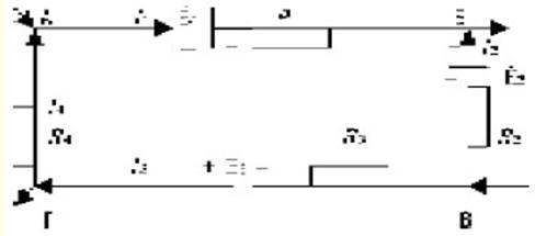 We arbitrarily choose the positive directions of the currents. We go around the contour from point A in an arbitrary direction, for example, clockwise. Consider section AB. In this area, a potential drop occurs (current flows from a point with a higher potential to a point with a lower potential). In section AB: ?A + E1 - I1R1=?B. On the BV site: ?B - E2 - I2R2 = ?C. On the VG section: ?B = I3R3 + E3 = ?G. On the HA site: ?G - I4R4 = ?BUT. Adding term by term the four above equations, we get: ?A + E1- I1R1 + ?B - E2 - I2R2 + ?C - I3R3 + E3 + ?G- I4R4 - ?B + ?C + ?G + ?A or E1 - I1R1 - E2 - I2R2 - I3R3 + E3 - I4R4 = 0. Transferring the product IR to the right side, we get: Ё1 - Ё2 + Ё3 = I1R1 + I2R2 + I3R3 + I4R4. This expression is the second Kirchhoff's law. The formula shows that in any closed circuit the algebraic sum of the electromotive forces is equal to the algebraic sum of the voltage drops. The overlay method is used to calculate electrical circuits that have several EMFs. The essence of the superposition method is that the current in any part of the circuit can be considered as consisting of a series of partial currents caused by each individual EMF, with the rest of the EMF being taken equal to zero. In problems, there are chains that have only two nodal points. An arbitrary number of branches can be included between the nodal points. The calculation of such circuits is greatly simplified by using the nodal voltage method. and \u1d (E1d2 + E2d3 + E3d1) / (d2 + d3 + d4 + dXNUMX). The numerator of the nodal voltage formula represents the algebraic sum of the products of the EMF of the branches. In the denominator of the formula, the sum of the conductivities of all branches is given. If the EMF of any branch has a direction opposite to that indicated in the diagram, then it is included in the formula for the nodal voltage with a minus sign. The loop current method is used to calculate complex electrical circuits with more than two nodal currents. The essence of the method lies in the assumption that each circuit has its own current. Then, in the common areas located on the border of two adjacent circuits, a current will flow equal to the algebraic sum of the currents of these circuits. 58. ELECTROLYSIS. THE FIRST AND SECOND FARADAY'S LAWS The current, passing through the liquid conductors, decomposes them into their component parts. Therefore, liquid conductors are called electrolytes. The decomposition of electrolytes under the action of an electric current is called electrolysis. Electrolysis is carried out in electroplating baths. galvanic bath is a vessel where a liquid is poured - an electrolyte, which is subjected to decomposition by current. Two plates (for example, carbon) are lowered into a vessel with electrolyte, which will be electrodes. We connect the negative pole of the DC source to one electrode (cathode), and the positive pole to the other electrode (anode) and close the circuit. The phenomenon of electrolysis will be accompanied by the release of a substance on the electrodes. During electrolysis, hydrogen and metals are always released at the cathode. From this it follows that the origin of the current through liquid conductors is associated with the movement of the atoms of the substance. A neutral molecule of a substance, falling into a solvent, breaks up (dissociates) into parts - ions that carry equal and opposite electric charges. This is explained by the fact that the force of interaction between charges placed in a medium with electrical permeability e decreases by a factor of e. Therefore, the forces that bind a molecule of a substance located in a solvent with a high electrical permeability weaken and thermal collisions of molecules are sufficient for them to begin to divide into ions, i.e. e. to dissociate. Along with the dissociation of molecules in solution, the reverse process occurs - the reunification of ions into neutral molecules (molization). Acids dissociate into positively charged hydrogen ions and negatively charged ions of the acid residue. Alkalis dissociate into metal ions and water residue ions. Salts dissociate into metal ions and acid residue ions. If a constant voltage is applied to the electrodes, an electric field is formed between the electrodes. Positively charged ions will move towards the cathode, negatively charged ions - towards the anode. Reaching the electrodes, the ions are neutralized. The phenomenon of electrolysis was studied by Faraday from the quantitative and qualitative side. He found that the amount of substance released during electrolysis on the electrodes is proportional to the current and the time of its passage, or, in other words, to the amount of substance that has flowed through the electrolyte. This is Faraday's first law. The same current, passing the same time through different electrolytes, releases different amounts of substance on the electrodes. The amount of a substance in milligrams released at the electrode with a current of 1A for 1s is called the electrochemical equivalent and is denoted b. Faraday's first law is expressed by the formula: m=a/t. The chemical equivalent (m) of a substance is the ratio of atomic weight (A) to valency (n): m = A / n. Faraday's second law shows on what properties of a substance the value of its electrochemical equivalent depends. Electrolysis has found wide application in engineering. 1. Coating of metals with a layer of another metal using electrolysis (electroplating). 2. Obtaining copies from objects using electrolysis (electroplating). 3. Refining (purification) of metals. 59. BATTERIES To power control circuits, protection devices, signaling, automation, emergency lighting, drives and holding coils of high-speed switches, auxiliary mechanisms at power stations and substations, there must be such a source of electrical energy, the operation of which would not depend on the state of the main units of the power plant or substation. This source of energy must ensure uninterrupted and accurate operation of these circuits both during normal operation of the installation and in case of an accident. Such a source of energy in power plants and substations is accumulator battery. A timely charged battery with a large capacity can power the pantographs during the entire time of the accident. Batteries are also used for lighting cars, railway cars, the movement of electric cars and submarines, for powering radio installations and various devices, in laboratories and for other purposes. The battery is a secondary source of electrical voltage, since, unlike galvanic cells, it can only give energy after a pre-charge. The battery is charged by being connected to a constant voltage source. As a result of the electrolysis process, the chemical state of the battery plates changes and a certain potential difference is established between them. The rechargeable battery is completed from a number of lead-acid or alkaline accumulators. A lead-acid battery consists of several positive and negative plates immersed in a container of electrolyte. The electrolyte is a solution of sulfuric acid in distilled water. Battery plates are superficial and massive. The surface plates are made from pure lead. To increase the surface area of the plates, they are made ribbed. Mass plates are a lead grating, into the cells of which lead oxides are smeared. To prevent the mass from falling out of the cells, the plate is covered on both sides with lead sheets with holes. Typically, the positive battery plate is made surface, and the negative is mass. Separate positive plates, as well as negative plates, are soldered into two blocks isolated from one another. In order for the positive plates to work on both sides, they are taken one more than the negative ones. There are two types of alkaline batteries: cadmium-nickel and iron-nickel. Alkaline battery plates are nickel-plated steel frames with cells in which bags of thin nickel-plated perforated steel are placed. The active mass is pressed into the bags. The vessel of alkaline batteries is a steel welded box, in the lid of which there are three holes: two for the withdrawal of clamps and one for filling the electrolyte and escaping gases. Advantages: deficient lead is not consumed; have great endurance and mechanical strength; with prolonged exposure, they bear small losses on self-discharge and do not deteriorate; emit less harmful gases and fumes; have less weight. Disadvantages: lower EMF; lower efficiency; higher cost. 60. ELECTRIC INCANDESCENT LAMPS The incandescent lamp was invented by a Russian scientist A.N. Lodygin and was first shown to them in 1873. The principle of operation of an incandescent lamp is based on the strong heating of a conductor (filament) when an electric current passes through it. In this case, the conductor begins to emit, in addition to thermal, also light energy. To prevent the filament from burning out, it must be moved into a glass flask from which air is pumped out. This is how the so-called hollow lamps are arranged. Initially, carbon filament, obtained by calcining plant fibers, was used as a filament. Lamps with such a filament emitted a weak, yellowish light, consuming power. The carbon filament, heated up to a temperature of 1700°, gradually burned out, which led to a relatively rapid death of the lamp. Carbon filament lamps are now out of use. Now, in incandescent lamps, instead of a carbon filament, a filament made from the refractory metals osmium or tungsten is used. A tungsten filament, heated up to 2200 ° in hollow lamps, emitting a brighter light, consumes less power than a carbon filament. Burnout of the filament is reduced if the glass bulb (cylinder) of the lamp is filled with a gas that does not support combustion, such as nitrogen or argon. Such lamps are called gas-filled. The temperature of the filament during operation of such a lamp reaches 2800 °. Our industry produces incandescent lighting lamps for voltages of 36, 110, 127 and 220 V. For special purposes, lamps are also made for other voltages. Incandescent lamps have a very low efficiency. In them, only about 4-5% of the total electrical energy consumed by the lamp is converted into light energy; the rest of the energy is converted into heat. Currently, gas-lighting lamps are widely used. They use the property of rarefied gases to glow when an electric current passes through them. The light emitted by a gas lamp depends on the nature of the gas. Neon gives red-orange, argon - blue-violet, helium - yellowish-pink light. The gaslight lamps are powered by high voltage alternating current obtained using transformers. These lamps have found application for signboards, advertisements, and illumination. Our industry also produces lamps containing rarefied mercury vapor in their glass tubes. By passing current through them, the vapors can be made to glow faintly. The inner surface of the lamp tube is coated with a special compound - a phosphor that glows under the action of the glow of mercury vapor. These lamps are called fluorescent lamps. At present, three types of fluorescent lamps are produced: fluorescent lamps used to illuminate places where color differentiation is necessary - printing, cotton industry, etc.; white light lamps for lighting industrial, office and residential premises; warm white lamps for lighting museums, theaters and art galleries. Fluorescent lamps are four times more efficient than conventional incandescent lamps. 61. ELECTRIC WELDING There are two types of electric welding: 1) arc; 2) electric resistance welding. Electric arc welding was invented by a Russian engineer N.N. Benardos in 1882 Arc welding uses the heat generated by an electric arc. When welding according to the Benardos method, one pole of the voltage source is connected to a carbon rod, and the other pole to the parts to be welded. A thin metal rod is introduced into the flame of an electric arc, which melts, and drops of molten metal, flowing down onto the parts and solidifying, form a welding seam. In 1891 a Russian engineer N.G. Slavyanov proposed another method of electric arc welding, which was most widely used. Electric welding according to the Slavyanov method is as follows. The carbon rod is replaced by a metal electrode. The electrode itself melts, and the molten metal, solidifying, connects the parts to be welded. After using the electrode, it is replaced with a new one. Before welding the part, it must be thoroughly cleaned of rust, scale, oil, dirt with a chisel, file, sandpaper. To create a stable arc and obtain a strong seam, metal electrodes are coated with special compounds. Such a coating also melts during the melting of the electrode and, pouring over the strongly heated surfaces of the parts to be welded, does not allow them to oxidize. Electric resistance welding. If you put two pieces of metal close together and pass a strong electric current through them, then due to the release of heat at the point of contact of the pieces (due to the high transient resistance), the latter are heated to a high temperature and welded. At present, electric welding, both arc and resistance, has firmly entered the industry and has become very widespread. They weld sheet and angle steel, beams and rails, masts and pipes, trusses and boilers, ships, etc. Welding is used to make new and repair old parts made of steel, cast iron and non-ferrous metals. New methods for the use of electric welding have been developed: underwater electric welding; automatic welding; welding with alternating current (the device has a special part - an oscillator, the purpose of which is to generate alternating current of high voltage and very high frequency, which ensures stable arc burning when welding thin and thick metal parts). When closing and opening a circuit breaker or circuit breaker, as well as closing and opening the contacts of devices and apparatuses, an electric spark that occurs between the contacts, and often the electric arc that follows it, melts the metal, and the contacts burn or weld, disrupting the operation of the installation. This phenomenon is called electrical erosion. The spark at its appearance, as it were, "gnaws" the metal. To combat the spark, sometimes a capacitor of a certain capacity is included between the contacts in parallel with the spark gap. Engineers B.R. Lazarenko and I.N. Lazarenko used the property of an electric spark to "gnaw metal" in an electroerosive installation designed by them. The operation of the installation is basically as follows. One wire from a voltage source is connected to the metal rod. The other wire is connected to the workpiece that is in the oil. A metal rod is made to vibrate. An electric spark that occurs between the rod and the part “gnaws” the part, making a hole in it that is the same as the shape of the rod section (hexagonal, square, triangular, etc.). 62. ELECTROMAGNETISM A magnetic field is one of the two sides of the electromagnetic field, excited by the electric charges of moving particles and a change in the electric field and characterized by a force effect on moving charged particles, and therefore on electric currents. The direction of the magnetic induction lines changes with a change in the direction of the current in the conductor. Magnetic induction lines around a conductor have the following properties: 1) the magnetic induction lines of a straight conductor are in the form of concentric circles; 2) the closer to the conductor, the denser the magnetic induction lines are; 3) magnetic induction (field intensity) depends on the magnitude of the current in the conductor; 4) the direction of the magnetic induction lines depends on the direction of the current in the conductor. The direction of magnetic induction lines around a conductor with current can be determined by the "rule of the gimlet". If a gimlet (corkscrew) with a right-hand thread moves forward in the direction of the current, then the direction of rotation of the handle will coincide with the direction of the magnetic induction lines around the conductor. The magnetic field is characterized by a magnetic induction vector, which has a certain magnitude and a certain direction in space. A line tangent to each point of which coincides with the direction of the magnetic induction vector is called the line of magnetic induction, or magnetic induction line. The product of magnetic induction by the size of the area perpendicular to the direction of the field (magnetic induction vector) is called the flux of the magnetic induction vector or simply magnetic flux and is denoted by the letter Ф: Ф = BS. The unit of measurement is weber (Wb). Solenoid A coiled conductor is called, through which an electric current is passed. To determine the poles of the solenoid, they use the "rule of the gimlet", applying it as follows: if you place the gimlet along the axis of the solenoid and rotate it in the direction of the current in the turns of the solenoid, then the translational movement of the gimlet will show the direction of the magnetic field. A solenoid with a steel (iron) core inside is called electromagnet. The magnetic field of an electromagnet is stronger than that of a solenoid because the piece of steel embedded in the solenoid is magnetized and the resulting magnetic field is amplified. The poles of an electromagnet can be determined, just like a solenoid, according to the "rule of the gimlet". The magnetic flux of a solenoid (electromagnet) increases with an increase in the number of turns and current in it. The magnetizing force depends on the product of the current and the number of turns. You can increase the magnetic flux of the solenoid in the following ways: 1) put a steel core into the solenoid, turning it into an electromagnet; 2) increase the cross section of the steel core of the electromagnet (because with a given current, magnetic field strength, and, therefore, magnetic induction, an increase in the cross section leads to an increase in the magnetic flux); 3) reduce the air gap of the electromagnet (because with a decrease in the path of the magnetic lines through the air, the magnetic resistance decreases). 63. ELECTROMAGNETIC INDUCTION The phenomenon of EMF in a circuit when it is crossed by a magnetic field is called electromagnetic induction and was discovered by an English physicist M. Faradeem in 1831 A conductor carrying an electric current is surrounded by a magnetic field. If you change the magnitude or direction of the current in the conductor, or open and close the electrical circuit that supplies the conductor with current, then the magnetic field surrounding the conductor will change. Changing, the magnetic field of the conductor crosses the same conductor and induces an EMF in it. This phenomenon is called self-induction. The induced emf itself is called self-induction emf. Induced EMF occurs in the following cases. 1. When a moving conductor crosses a fixed magnetic field or, conversely, a moving magnetic field crosses a fixed conductor; or when a conductor and a magnetic field, moving in space, move relative to the other. 2. When an alternating magnetic field of one conductor, acting on another conductor, induces an EMF in it. 3. When the changing magnetic field of the conductor induces an EMF in it (self-induction). To determine the induced EMF in the conductor, the “right hand rule” is used: if you mentally place your right hand in a magnetic field along the conductor so that the magnetic lines coming out of the north pole enter the palm, and the bent thumb coincides with the direction of movement of the conductor, then four the outstretched fingers will show the direction of the induced emf in the conductor. The value of the induced emf in the conductor depends on: 1) on the magnitude of the induction of the magnetic field, since the denser the magnetic induction lines are, the greater the number of them will cross the conductor per unit time; 2) on the speed of the conductor in a magnetic field, since at a high speed of movement the conductor can cross more induction lines per unit time; 3) on the working (located in a magnetic field) length of the conductor, since a long conductor can cross more induction lines per unit time; 4) on the value of the sine of the angle between the direction of movement of the conductor and the direction of the magnetic field. In 1834 a Russian academician E.Kh. Lenz gave a universal rule for determining the direction of the induced emf in a conductor. This rule, known as Lenz's rule, is formulated as follows: the direction of the induced emf is always the same, that the current caused by it and its magnetic field are in such a direction that they tend to interfere with the cause that generates this induced emf. The currents that are induced in metallic bodies when they are crossed by magnetic lines are called eddy currents, or Foucault currents. To reduce eddy current losses, the armatures of generators, electric motors and transformer cores are assembled from separate thin (0,35-0,5 mm) stamped sheets of mild steel, located in the direction of the magnetic flux lines and insulated from one another with varnish or thin paper. This is done in order to reduce the magnitude of the magnetic flux passing through it due to the small cross section of each steel sheet, and therefore, to reduce the EMF and current induced in it. Eddy currents are useful. These currents are used for hardening steel products with high frequency currents in the operation of induction electrical measuring instruments, meters and AC relays. 64. RECEIVING AC CURRENT Let there be a uniform magnetic field formed between the poles of an electromagnet. Inside the field, under the action of an external force, a metal rectilinear conductor rotates in a circle in the direction of clockwise movement. The intersection of conductors of magnetic lines will lead to the appearance of an induced emf in the conductor. The value of this EMF depends on the magnitude of the magnetic induction, the active length of the conductor, the speed at which the conductor crosses magnetic lines, and the sine of the angle between the direction of movement of the conductor and the direction of the magnetic field. ?= Bl?sin?. We decompose the peripheral speed into two components - normal and tangential with respect to the direction of magnetic induction. The normal component of the velocity determines the induced EMF of induction and is equal to: ?n = ?sin?. The tangential velocity component does not take part in the creation of the induced EMF and is equal to: When moving, the conductor will occupy various positions. For one complete revolution of the conductor, the EMF in it first increases from zero to a maximum value, then decreases to zero and, changing its direction, increases again to a maximum value and again decreases to zero. With further movement of the conductor, changes in the EMF will be repeated. A current that varies in magnitude and direction will flow in the external circuit. This current is called variable Unlike permanent, which give galvanic cells and batteries. Variable EMF and alternating current periodically change their direction and magnitude. The value of a variable (current, voltage and EMF) at a given point in time is called the instantaneous value. The largest of the instantaneous values of a variable is called its maximum, or amplitude, value and is denoted by Im, Um. The period of time after which changes in the variable are repeated is called the period T (measured in seconds). The number of periods per unit time is called the frequency of the alternating current and is denoted by v (measured in hertz). In engineering, currents of various frequencies are used. The standard industrial frequency in Russia is -50 Hz. EMF in the conductor is induced according to the sine law. This EMF is called sinusoidal. The alternating sinusoidal current during the period has different instantaneous values. The actions of the current are not determined by either amplitude or instantaneous values. To evaluate the effect produced by alternating current, we compare it with the thermal effect of direct current. The DC power passing through the resistance will be C = I2R. The relationship between the effective and peak values of the current strength and AC voltage has the form: Im = I?2, Um = U?2. The effective value of an alternating current is equal to such a direct current, which, passing through the same resistance as the alternating current, releases the same amount of energy in the same time. 65. AC CIRCUITS Consider a circuit consisting of resistance R. For simplicity, we neglect the influence of inductance and capacitance. A sinusoidal voltage u = Umsin?t is applied to the circuit terminals. According to Ohm's law, the instantaneous value of the current will be: i \uXNUMXd u / r =(Um / r)sin?t = Im sin?t. The power formula for an AC circuit with active resistance is the same as the power formula for a DC circuit: P \u2d IXNUMXR. All conductors have active resistance. In an alternating current circuit, the filaments of incandescent lamps, spirals of electric heaters and rheostats, arc lamps and long straight conductors have almost only one active resistance. Consider an AC circuit containing a coil with inductance L without a steel core. For simplicity, we will assume that the active resistance of the coil is very small and can be neglected. With the greatest speed, the current changes around its zero values. Near the maximum values, the rate of change of the current decreases, and at the maximum value of the current, its increase is equal to zero. Thus, alternating current varies not only in magnitude and direction, but also in the rate of its change. An alternating current, passing through the turns of the coil, creates an alternating magnetic field. The magnetic lines of this field, crossing the turns of their own coil, induce an EMF of self-induction in them. Since the inductance of the coil in our case remains unchanged, the EMF of self-induction will depend only on the rate of change of current. The highest rate of current change occurs near zero current values. Consequently, the EMF of self-induction has the greatest value at the same moments. At the initial moment of time, the current sharply and rapidly increases from zero, and therefore has a negative maximum value. Since the current increases, the EMF of self-induction, according to the Lenz rule, should prevent the current from changing. Therefore, the EMF of self-induction with increasing current will have a direction opposite to the current. The rate of current change decreases as it approaches the maximum. Therefore, the EMF of self-induction also decreases, until, finally, at the maximum current, when its changes are equal to zero, it becomes equal to zero. The alternating current, having reached a maximum, begins to decrease. According to Lenz's rule, the EMF of self-induction will prevent the current from decreasing and, already directed in the direction of current flow, will support it. With a further change, the alternating current rapidly decreases to zero. A sharp decrease in the current in the coil will also entail a rapid decrease in the magnetic field, and as a result of the intersection of the magnetic lines of the turns of the coil, the largest EMF of self-induction will be induced in them. Since the self-induction EMF in alternating current circuits continuously counteracts changes in current, in order to allow current to flow through the turns of the coil, the mains voltage must balance the self-induction EMF. That is, the voltage of the network at each moment of time must be equal and opposite to the EMF of self-induction. The value XL = ?L is called inductive reactance, which is a kind of obstacle that the circuit has to change the current in it. The value XC = 1/(?C) is called capacitive resistance, which, like inductive reactance, depends on the frequency of the alternating current. 66. OSCILLATORY CIRCUIT Consider the case of obtaining alternating current by discharging a capacitor to a coil. A charged capacitor has a store of electrical energy. When shorted to the coil, it will begin to discharge and the supply of electrical energy in it will decrease. The discharge current of the capacitor, passing through the turns of the coil, creates a magnetic field. Consequently, the coil will begin to store magnetic energy. When the capacitor is fully discharged, its electrical energy will become zero. At this moment, the coil will have a maximum supply of magnetic energy. Now the coil itself becomes a generator of electric current and begins to recharge the capacitor. The self-induction emf that occurs in the coil during the period of magnetic field growth prevented the current from increasing. Now, when the magnetic field of the coil will decrease, the EMF of self-induction tends to maintain the current in the same direction. At the moment when the magnetic energy of the coil becomes equal to zero, the capacitor plates will be charged opposite to how they were charged at the beginning, and if the resistance of the circuit is zero, then the capacitor will receive the initial supply of electrical energy. Then the capacitor will receive the initial supply of electrical energy. Then the capacitor will begin to discharge again, creating a reverse current in the circuit, and the process will be repeated. The alternating transformations of electrical energy into magnetic energy and vice versa form the basis of the process of electromagnetic oscillations. A circuit consisting of capacitance and inductance in which the process of electromagnetic oscillations occurs is called oscillatory circuit. Periodic energy fluctuations occurring in an oscillatory circuit could continue indefinitely in the form of undamped oscillations if there were no losses in the oscillatory circuit itself. However, the presence of active resistance leads to the fact that the energy reserve of the circuit decreases with each period due to heat losses in the active resistance, as a result of which the oscillations die out. The period of electromagnetic oscillations occurring in an oscillatory circuit without resistance is determined by the Thomson formula. There are two ways to change the time of the oscillation period of the circuit - by changing the inductance of the coil or the capacitance of the capacitor. Both methods are used for this purpose in radio engineering. An oscillatory circuit is a necessary accessory for every radio receiver and radio transmitter. The principle of radio transmission is as follows. Electromagnetic oscillations are created in the antenna of the transmitting radio station with the help of tube generators. The amplitude of oscillation depends on a number of factors, including the amount of current flowing in the microphone circuit, which receives sound vibrations due to speech or music. Changes in high frequency vibrations with the help of sound vibrations are called modulation. Radio communication was first carried out by an outstanding Russian scientist A.S. Popov (1859-1905). 67. THREE-PHASE AC Polyphase system called a set of variable EMF of the same frequency and shifted in phase one relative to the other by any angles. Each EMF can operate in its own circuit and not be associated with other EMF. Such a system is called unrelated. The disadvantage of an uncoupled multi-phase system is a large number of wires, equal to 2m. So, for example, six wires are required to transmit power through a three-phase system. A polyphase system in which the individual phases are electrically connected to each other is called a coupled polyphase system. Polyphase current has important advantages: 1) when transferring the same power by multi-phase current, a smaller cross-section of wires is required than with a single-phase current; 2) with the help of fixed coils or windings, it creates a rotating magnetic field used in the operation of motors and various AC devices. Of the multi-phase current systems, three-phase alternating current has received the most practical application. It turns out as follows. If three turns are placed in a uniform magnetic field of the poles, each of them is located at an angle of 120 ° with respect to the other, and the turns are rotated at a constant angular velocity, then an EMF will be induced in the turns, which will also be shifted in phase by 120 °. In practice, to obtain a three-phase current, three windings are made on the stator of an alternator, shifted one relative to the other by 120 °. They are called phase windings or simply generator phases. An uncoupled three-phase current system is not used in practice. The phase windings of generators and consumers of three-phase current are connected according to the star or delta scheme. If the phase windings of the generator or consumer are connected so that the ends of the windings are closed to one common point, and the beginnings of the windings are connected to linear wires, then such a connection is called star. In star connection, the line voltage is V3 times the phase voltage. With an uneven load, the phase voltages of the consumer are different in magnitude, and the magnitude of the phase voltage is proportional to the phase resistance. The displacement of the zero point of the consumer, which occurs as a result of an uneven load, leads to an undesirable phenomenon in lighting networks. The greater the number and power of the lamps included in the phase, the lower their resistance will be, the lower their phase voltage will be, the weaker they will burn. In addition to the star connection, generators or three-phase current consumers can be switched on triangle. With a uniform delta load, the line current is V3 times the phase current. In motors and other consumers of three-phase current, in most cases, all six ends of the three windings are output, which, if desired, can be connected either with a star or a triangle. Usually, a board of insulating material (terminal board) is attached to a three-phase machine, to which all six ends are brought out. The power of a three-phase system can be calculated using the formula: P = ?3 IUcos ?. 68. TRANSFORMERS In 1876 P.I. Yablochkov suggested using a transformer to power the candles. In the future, the design of transformers was developed by another Russian inventor, a mechanic I.F. Usagin, who suggested using transformers to power not only Yablochkov candles, but also other consumers of electrical energy. A transformer is an electrical device based on the phenomenon of mutual induction and designed to convert alternating current of one voltage into alternating current of a different voltage, but of the same frequency. The simplest transformer has a steel core and two windings insulated both from the core and from each other. The winding of a transformer that is connected to a voltage source is called primary winding, and the winding to which consumers are connected or transmission lines leading to consumers is called secondary winding. An alternating current, passing through the primary winding, creates an alternating magnetic flux, which interlocks with the turns of the secondary winding and induces an emf in them. Since the magnetic flux is variable, the induced EMF in the secondary winding of the transformer is also variable and its frequency is equal to the frequency of the current in the primary winding. The variable magnetic flux passing through the core of the transformer crosses not only the secondary winding, but also the primary winding of the transformer. Therefore, an EMF will also be induced in the primary winding. The magnitude of the EMF induced in the windings of the transformer depends on the frequency of the alternating current, the number of turns of each winding and the magnitude of the magnetic flux in the core. At a certain frequency and a constant magnetic flux, the value of the EMF of each winding depends only on the number of turns of this winding. This relationship between the EMF values and the number of turns of the transformer windings can be expressed by the formula: The difference between EMF and voltage is so small that the relationship between voltages and the number of turns of both windings can be expressed by the formula: U1 / U2 = N1 / N2. The difference between EMF and voltage in the primary winding of the transformer becomes especially small when the secondary winding is open and the current in it is zero (idle), and only a small current flows in the primary winding, called the no-load current. In this case, the voltage at the terminals of the secondary winding is equal to the EMF induced in it. The number showing how many times the voltage in the primary winding is greater (or less) than the voltage in the secondary winding is called the transformation ratio and is denoted by the letter k. k = U1 / U2 ? N1 / N2. The rated voltage of the high and low voltage windings, indicated on the nameplate of the transformer, refers to the idling mode. Transformers that serve to increase the voltage are called step-up; their transformation ratio is less than one. Step-down transformers step down the voltage; their transformation ratio is greater than one. The mode in which the secondary winding of the transformer is open, and an alternating voltage is applied to the terminals of the primary winding, is called idle or idle operation of the transformer. 69. DEVICE AND TYPES OF TRANSFORMERS The core (magnetic circuit) of the transformer forms a circuit closed for the magnetic flux and is made of sheet electrical (transformer) steel with a thickness of 0,5 and 0,35 mm. Electrical steel is steel that contains 4-4,8% silicon by weight. The presence of silicon improves the magnetic properties of steel and increases its resistivity to eddy currents. Separate sheets of steel are coated with a layer of varnish to isolate them from one another, after which they are tightened with bolts passed in insulating bushings. Such a device is used to reduce eddy currents induced in steel by an alternating magnetic flux. The parts of the magnetic circuit on which the winding is put on are called rods. The rods are connected by the upper and lower yokes. According to the design of the magnetic circuit, two types of transformers are distinguished: rod and armored. In a rod-type transformer, the windings cover the rods of the magnetic core; in armored transformers, the magnetic circuit, on the contrary, as "armor", covers the windings. In the event of a fault in the winding of an armored transformer, it is inconvenient to inspect and difficult to repair. Therefore, the most widespread are rod-type transformers. The winding of the transformer is made of insulated round or rectangular copper. An insulating (usually cardboard impregnated with bakelite varnish) cylinder is first put on the core of the magnetic circuit, on which a low-voltage winding is placed. The location of the low voltage winding closer to the rod is explained by the fact that it is easier to isolate it from the steel rod than the high voltage winding. Another insulating cylinder is put on the superimposed low voltage winding, on which the high voltage winding is placed. Such transformers are called two-winding. There are transformers that have one primary and two secondary windings per phase. The primary winding is the higher voltage winding. The secondary windings, depending on the magnitude of the voltage at their terminals, are called: one is the medium voltage winding and the other is the low voltage winding. Such transformers are called three-winding. For the transformation of three-phase current, you can use single-phase transformers. If we combine the steel of three cores into one common core, we get the core of a three-phase transformer. The cost of transformer steel for a three-phase transformer is much less than for the installation of three single-phase transformers. If the power required for the transformation is greater than the power of one transformer, then in this case several transformers are switched on for parallel operation. To enable parallel operation of single-phase transformers, the following conditions must be met. 1. The voltages of the primary and secondary windings of transformers connected in parallel must be equal. In this case, the transformation ratios of the transformers will also be equal. 2. Equality of short circuit voltages. 3. Switching on by the same phases from the side of the higher and lower voltages. An autotransformer is a transformer that has only one winding on its core. Both primary and secondary circuits are connected to various points of this winding. The magnetic flux of an autotransformer induces an electrical force in the winding. This electromotive force is almost equal to the applied voltage. 70. ASYNCHRONOUS MOTORS asynchronous machine an alternating current machine is called, in which the rotor rotation speed is less than the rotation speed of the stator magnetic field and depends on the load. An asynchronous machine, like other electrical machines, has the property of reversibility, i.e., it can operate both in motor mode and in generator mode. The three-phase induction motor was invented by the Russian engineer M.O. Dolivo-Dobrovolsky in 1890 and since then, undergoing improvements, has firmly taken its place in industry and has become widespread in all countries of the world. An induction motor has two main parts - stator and rotor. The stator is the fixed part of the machine. Grooves are made on the inside of the stator, where a three-phase winding is placed, fed by a three-phase alternating current. The rotating part of the machine is called the rotor, the winding is also laid in its grooves. The stator and rotor are assembled from separate stamped sheets of electrical steel with a thickness of 0,35 and 0,5 mm. Individual sheets of steel are isolated from each other with a layer of varnish. The air gap between the stator and the rotor is made as small as possible. Depending on the design of the rotor, asynchronous motors come with squirrel-cage and phase rotors. Asynchronous motors are divided into brushless and collector. Brushless motors are the most widely used. They are used where an approximately constant speed of rotation is required and its adjustment is not required. Brushless motors are simple in design, trouble-free in operation and have high efficiency. If you connect the processing of the stator to a three-phase alternating current network, then a rotating magnetic field arises inside the stator. The magnetic lines of the field will cross the winding of the fixed current of the rotor and induce an EMF in it. The rotor, during its rotation, cannot catch up with the rotating magnetic field of the stator. If we assume that the rotor will have the same rotational speed as the stator magnetic field, then the currents in the rotor winding will disappear. With the disappearance of currents in the rotor winding, their interaction with the stator field will stop and the rotor will begin to rotate more slowly than the rotating stator field. However, in this case, the rotor winding will again begin to be crossed by the rotating field of the stator and the torque will again act on the rotor. Consequently, during its rotation, the rotor must always lag behind the rotation speed of the stator magnetic field, i.e. rotate asynchronously (not in time with the magnetic field), which is why these motors were named asynchronous. The squirrel-cage induction motor is the most common of the electrical motors used in industry. The device of an asynchronous motor is as follows. A three-phase winding is placed on the stationary part of the motor - the stator, fed by a three-phase current. The beginnings of the three phases of this winding are displayed on a common shield, mounted on the outside of the motor housing. Since an alternating current flows in the stator windings, an alternating magnetic flux will pass through the stator steel. To reduce the eddy currents that occur in the stator, it is made from separate stamped sheets of alloy steel with a thickness of 0,35 and 0,5 mm. Disadvantages: difficulty in adjusting the rotation speed and high starting current. Therefore, along with them, asynchronous motors with a phase rotor are also used. The device of the stator of such a motor and its winding do not differ from the device of the stator of a motor with a squirrel-cage rotor. The difference between these two engines lies in the design of the rotor. An electric motor with a phase rotor has a rotor, on which, like on the stator, three phase windings are placed, interconnected by a star. 71. SYNCHRONOUS GENERATORS Synchronous machine a machine is called, the rotation speed of which is constant and is determined at a given frequency of alternating current by the number of pairs of poles p: v \u60d XNUMX ·n / p. According to the principle of reversibility, discovered by E.Kh. Lenz, a synchronous machine can operate both as a generator and as a motor. The operation of synchronous generators is based on the phenomenon of electromagnetic induction. Since it is fundamentally indifferent whether a moving conductor crosses a fixed magnetic field, or, conversely, a moving field crosses a fixed conductor, structurally synchronous generators can be made in two types. In the first of them, the magnetic poles can be placed on the stator and feed their winding with direct current, and the conductors can be placed on the rotor and removed from them using rings and brushes with alternating current. Often, that part of the machine that creates a magnetic field is called an inductor, and that part of the machine where the winding is located, in which the EMF is induced, is called an armature. Therefore, in the first type of generator, the inductor is stationary, and the armature rotates. The stator of a synchronous generator, like other AC machines, consists of a core made of sheets of electrical steel, in the grooves of which an alternating current winding is laid, and a frame - a cast-iron or welded casing from sheet steel. The stator winding is placed in the grooves stamped on the inner surface of the core. The insulation of the winding is carried out with particular care, since the machine usually has to work at high voltages. Micanite and micanite tape are used as insulation. The rotors of synchronous machines are divided into two types by design: 1) explicit poles (i.e., with pronounced poles); 2) implicitly polar (i.e., with implicitly expressed poles). The salient pole rotor is a steel forging. Poles are attached to the rotor rim, on which excitation coils are put on, connected in series with each other. The ends of the excitation winding are connected to two rings mounted on the rotor shaft. Brushes are superimposed on the rings, to which a constant voltage source is connected. Usually, a direct current generator, sitting on the same shaft with the rotor and called the exciter, gives a direct current to excite the rotor. The exciter power is 0,25-1% of the nominal power of the synchronous generator. Rated voltage of exciters 60-350 V. Self-excited synchronous generators are also available. A direct current to excite the rotor is obtained using selenium rectifiers connected to the generator stator winding. At the first moment, the residual magnetic field of the rotating rotor induces a small variable EMF in the stator winding. Selenium rectifiers connected to alternating voltage give a direct current, which strengthens the field of the rotor, and the voltage of the generator increases. When designing electrical machines and transformers, designers pay great attention to the ventilation of machines. For synchronous generators, air and hydrogen cooling is used. 72. DC GENERATOR DEVICE The DC generator is an electrical machine that converts the mechanical energy of the primary engine rotating it into direct current electrical energy, which the machine gives to consumers. The DC generator works on the principle electromagnetic induction. Therefore, the main parts of the generator are an armature with a winding located on it and electromagnets that create a magnetic field. The anchor has the shape of a cylinder and is recruited from separate stamped sheets of electrical steel with a thickness of 0,5 mm. The sheets are isolated from each other by a layer of varnish or thin paper. The depressions, stamped around the circumference of each sheet, form grooves when assembling the armature and compressing the sheets, where the insulated conductors of the armature winding are laid. A collector is fixed on the armature shaft, consisting of separate copper plates soldered to certain places of the armature winding. The collector plates are isolated from each other by micanite. The collector serves to rectify the current and divert it with the help of fixed brushes to the external network. DC generator electromagnets consist of steel pole cores bolted to the frame. The generator frame is cast from steel. For machines of very low power, the frame is cast together with the pole cores. In other cases, the cores of the poles are recruited from separate sheets of electrical steel. Coils made of insulated copper wire are put on the cores. The direct current passed through the excitation winding creates a magnetic flux of the poles. For a better distribution of the magnetic flux in the air gap, poles with tips are attached to the yoke, assembledifrom individual steel sheets. When the armature rotates in a magnetic field of pluses, an EMF is induced in the conductor of its winding, variable in magnitude and direction. If the ends of one turn are soldered to two copper rings, brushes connected to an external network are applied to the rings, then when the turn rotates in a magnetic field, an alternating electric current will flow in a closed circuit. This is the basis for the operation of alternators. If the ends of the coil are attached to two copper half-rings, isolated from each other and called collector plates, and brushes are applied to them, then when the coil rotates in a magnetic field, an alternating EMF will still be induced in the coil. However, in the external circuit, a constant direction current of varying magnitude (pulsating current) will flow. The neutral line, or geometric neutral, is the line passing through the center of the armature and perpendicular to the axis of the poles. The active side of the coil in this position slides along the magnetic lines without crossing them. Therefore, no EMF is induced in the coil and the current in the circuit is zero. The width of the brush is greater than the width of the collector division formed by the plate and the insulating gap, and the coil, being on the neutral line, is short-circuited at this moment of the brush. For generators operating with a rapidly changing load (cranes, rolling mills), sometimes a compensation winding is used, which is laid in grooves specially made in the pole pieces. The direction of the current in the compensation winding must be opposite to the current in the conductors of the armature winding. On the arc covered by the pole piece, the magnetic field of the compensating winding will balance the armature reaction field, preventing the machine field from being distorted. The compensation winding, as well as the winding of the additional poles, is connected in series with the armature winding. 73. TYPES OF DC GENERATORS Depending on the method of creating a magnetic field, DC generators are divided into three groups: 1) generators with permanent magnets, or magnetoelectric; 2) generators with independent excitation; 3) generators with self-excitation. Magnetoelectric generators consist of one or more permanent magnets, in the field of which an armature with a winding rotates. Due to the very low power generated, generators of this type are not used for industrial purposes. In a generator with independent excitation, the pole windings are powered by an external source of constant voltage independent of the generator (DC generator, rectifier, etc.). The excitation winding of the generator poles with self-excitation is supplied from the armature brushes of the machine itself. The principle of self-excitation is as follows. In the absence of current in the excitation winding, the generator armature rotates in a weak magnetic field of residual magnetism of the poles. The independent EMF induced in the armature winding at this moment sends a small current into the pole winding. The magnetic field of the poles increases, causing the EMF in the armature conductors to also increase, which in turn will cause an increase in the excitation current. This will continue until a current is established in the excitation winding corresponding to the resistance value of the excitation circuit. Self-excitation of the machine can only occur if the current flowing through the winding of the poles will create a magnetic field that enhances the field of residual magnetism, and if, in addition, the resistance of the excitation circuit does not exceed a certain certain value. Self-excited generators, depending on the method of connecting the field winding to the armature winding, are divided into three types. 1. A generator with parallel excitation (shunt), in which the excitation winding of the poles is connected in parallel with the armature winding. 2. Generator with serial excitation (series), in which the excitation winding of the poles is connected in series with the armature winding. 3. Generator with mixed excitation (compound), which has two windings on the poles: one is connected in parallel with the armature winding, and the other is connected in series with the armature winding. The voltage of an independently excited generator changes with load for two reasons: 1) due to a voltage drop in the armature winding and the transition contact of the brushes; 2) the action of the armature reaction, leading to a decrease in the magnetic flux and EMF of the machine. For a generator with parallel excitation, the voltage with the load changes from three reasons: 1) due to a voltage drop in the armature winding and the transition contact of the brushes; 2) due to a decrease in the magnetic flux caused by the action of the armature reaction; 3) under the influence of the first two reasons, the voltage of the generator (or the voltage of the armature brushes) decreases with the load. A generator with serial excitation differs from a generator with parallel excitation, since the voltage of the former increases with increasing load, while that of the latter decreases. A mixed excitation generator combines the properties of parallel and series excitation generators. 74. ELECTRIC MOTORS If a DC machine is connected to a voltage source, then it will work with an electric motor, i.e., convert electrical energy into mechanical energy. This property of electrical machines to work both as a generator and as an engine is called reversibility. The electric motor was invented in 1834 by a Russian academician B.S. Jacobi. The device of electric motors is the same as generators. The principle of operation of DC electric motors is based on the interaction of the current flowing in the armature winding and the magnetic field created by the poles of electromagnets. The power consumed by the motor from the network is greater than the power on the shaft by the amount of friction losses in bearings, brushes on the collector, armatures on air, losses in steel due to hysteresis and eddy currents, power losses for heating the motor windings and rheostats. The efficiency of an electric motor changes with load. At rated power, the efficiency of the motors ranges from 70 to 93%, depending on the power, rotation speed and design of the motors. Depending on the connection of the armature winding and the excitation winding, DC electric motors are divided into motors with parallel, series and mixed excitation. The conductors of the armature winding, through which the current passes, being in the magnetic field created by the poles, experience a force under the action of which they are pushed out of the magnetic field. In order for the motor armature to rotate in any particular direction, it is necessary that the direction of the current in the conductor changes to the opposite, as soon as the conductor leaves the coverage area of one pole, crosses the neutral line and enters the coverage area of \uXNUMXb\uXNUMXba neighboring, opposite pole. To direct the current in the conductors of the motor armature winding at the moment when the conductors pass the neutral line, a collector is used. In an electric motor with parallel excitation, the field winding is connected in parallel to the network, and with a constant resistance of the excitation circuit and network voltage, the magnetic flux of the motor must be constant. As the motor load increases, the armature reaction weakens the magnetic flux, which leads to some increase in speed. In practice, the voltage drop in the armature winding is selected so that its effect on the motor speed is almost compensated by the armature reaction. A characteristic property of a motor with parallel excitation is an almost constant speed of rotation when the load on its shaft changes. For motors with series excitation, the armature and excitation windings are connected in series. Therefore, the current flowing through both motor windings will be the same. At low saturations of the steel of the motor magnetic circuit, the magnetic flux is proportional to the armature current. In an electric motor with mixed excitation, the presence of two windings on the motor poles allows you to use the advantages of parallel and mixed excitation motors. These advantages are constant speed and high starting torque. The speed control of the motor with mixed excitation is carried out by an adjusting rheostat included in the circuit of the parallel excitation winding. 75. RECTIFIERS Engine generators rarely used and usually use special devices that convert alternating current to direct current and are called rectifiers. In engineering, two types of rectifiers are most widely used: 1) solid rectifiers; 2) mercury rectifiers. Solid rectifiers are called those in which individual parts are made of solid bodies. From solid rectifiers, copper-oxide (cuprox), selenium, silicon and germanium have become widespread in technology. Mercury rectifiers are: 1) glass; 2) metal. In addition to solid and mercury rectifiers, there are also rectifiers: mechanical, kenotrons, gastrons, electrolytic. Kenotrons (tube rectifiers) are widely used in radio engineering, they are found in most modern radio receivers powered by AC networks, etc. Copper-oxide (cuprox) rectifiers consist of three layers: 1) a metal that has free electrons in high concentration; 2) insulating (locking), not having free electrons; 3) a semiconductor having a small number of free electrons. If there is a potential difference on small layers, a strong electric field arises in the blocking layer, which contributes to the ejection of free electrons from the layers adjacent to it. In selenium rectifiers, one electrode is a nickel-plated iron washer coated with a thin layer of selenium. The second electrode is a layer of a special, highly conductive alloy of bismuth, tin, and cadmium deposited on selenium. A contact brass washer is pressed against this layer. To include the element in the circuit, plates touching both electrodes are used. A barrier layer appears at the boundary between the cover layer and the selenium layer. The action of a mercury rectifier is based on the so-called valve (one-sided) ability of an electric arc that has arisen in a vessel evacuated and filled with mercury to pass current in only one direction. A valve is a device that has low resistance for forward current and high resistance for reverse current. For currents above 500 A, metal mercury rectifiers are used. The metal case of the rectifier is water-cooled. The cathode cup, isolated from the body, is filled with mercury. The main anodes are passed through anode sleeves, which protect the anodes from mercury condensed from its vapors. The ignition anode and independent excitation anodes are placed inside the rectifier. The top end of the ignition anode is attached to a steel core placed in the solenoid. If you close the current circuit that feeds the solenoid, then the core is drawn in and lowers the ignition anode, which is immersed in mercury for a short time and then returns to its previous position under the action of the spring. The arc that has arisen between the ignition anode and mercury is transferred to the excitation anodes, which support the arc, preventing it from extinguishing. Adjustment of the rectified voltage at the rectifiers is carried out using a sectioned transformer or autotransformer, which has a number of branches from its windings. By changing the value of the AC voltage supplying the rectifier, the value of the rectified voltage is changed. 76. ELECTRICAL INSTRUMENTS To measure electrical quantities, special electrical measuring instruments are used. Electrical measuring instruments have found wide application for the rational operation, control and protection of electrical installations in various sectors of the national economy. In electrical measuring instruments, there are movable and fixed parts of the device. The manifestation of electric current, for example, its thermal, magnetic and mechanical effects, are the basis for the interaction of the moving and stationary parts of the device. The resulting torque turns the movable part of the device together with the pointer (arrow). Under the action of a torque, the movable system rotates through an angle that is greater, the greater the measured value. In contrast to the torque, an equal and opposite counteracting moment must be created, since otherwise, for any value of the measured value (except zero), the arrow will deviate to the end of the scale until it stops. Typically, the counter torque is generated using phosphor bronze helical springs. Friction, as you know, is always directed against the motion. Therefore, when the moving part of the device moves, friction will interfere with this and distort the readings of the device. To reduce friction, the moving part in some designs is mounted on cores in thrust bearings made of high-hard stone (ruby, sapphire, agate). To protect cores and thrust bearings from destruction during transfer or transportation, some devices have a device called caged, which lifts the movable part and fixes it motionless. Under the influence of certain reasons, the counteracting moment of the device changes. For example, at different temperatures, coil springs have unequal elasticity. In this case, the arrow of the device will move away from the zero division. To set the arrow to the zero position, a device called a corrector is used. The measuring mechanism of the device is enclosed in a housing that protects it from mechanical influences and ingress of dust, water, gases. One of the conditions for the device is the rapid calming of its moving part, achieved by installing dampers using the mechanical resistance of the medium (air, oil) or magnetic induction braking. Electrical measuring instruments are distinguished by the following features: 1) by the nature of the measured value; 2) by the type of current; 3) according to the degree of accuracy; 4) according to the principle of action; 5) according to the method of obtaining a reading; 6) by the nature of the application. In addition to these features, electrical measuring instruments can also be distinguished: 1) by mounting method; 2) a method of protection against external magnetic or electric fields; 3) endurance in relation to overloads; 4) suitability for use at various temperatures; 5) overall dimensions and other features. According to the type of current, the devices are divided into direct current devices, alternating current devices and direct and alternating current devices. According to the principle of operation, devices are divided into magnetoelectric, electromagnetic, electrodynamic (ferrodynamic), induction, thermal, vibration, thermoelectric, detector, etc. 77. DEVICE OF MEASURING INSTRUMENTS Devices of the magnetoelectric system operate on the principle of interaction of a coil with current and the field of a permanent magnet. A strong permanent horseshoe magnet made of cobalt, tungsten or nickel-aluminum steel creates a magnetic field. To the ends of the magnet are pole pieces made of mild steel with cylindrical grooves. A steel cylinder is fixed between the pole pieces, which serves to reduce the resistance of the magnetic circuit. The magnetic lines leave the pole pieces and, due to the fact that the magnetic permeability of steel is much greater than that of air, they radically enter the cylinder, forming an almost uniform magnetic field in the air gap. The same field is created when the magnetic lines exit the cylinder. The cylinder is surrounded by a light aluminum frame with a winding (coil) wound on it, made of insulated copper wire. The frame sits on an axis lying in thrust bearings. An aluminum arrow is also attached to the axis. The counteracting moment is created by two flat coil springs, which simultaneously serve to supply current to the winding of the device. Electromagnetic devices work on the principle of interaction between the coil current and the magnetic field of a moving core made of ferromagnetic material. By design, electromagnetic devices are divided into two types: devices with a flat coil and devices with a round coil. The principle of operation of electrodynamic devices is based on the interaction of the magnetic fields of two coils: one, fixed, and the other, sitting on an axis and turning. The principle of operation of thermal devices is based on the elongation of a metal thread when heated by current, which is then converted into a rotational movement of the moving part of the device. Inductive measuring instruments are characterized by the use of several fixed coils, fed with alternating current, and creating a rotating or running magnetic field, which induces currents in the moving part of the instrument and causes it to move. Induction devices are used only with alternating current as wattmeters and electricity meters. The principle of operation of devices of a thermoelectric system is based on the use of an electromotive force that arises in a circuit consisting of dissimilar conductors, if the junction of these conductors has a temperature different from the temperature of the rest of the circuit. The devices of the detector system are a combination of a magnetoelectric measuring device and one or more semiconductor rectifiers (detectors) connected together in one circuit. Copper-oxide rectifiers are usually used as rectifiers. Vibratory system instruments are characterized by the use of a number of tuned plates having different periods of natural oscillations and allowing the measurement of frequency due to the resonance of the frequency of the oscillating plate with the measured frequency. Vibrating devices are built only as frequency meters. 78. INSTRUMENT TRANSFORMERS In AC networks, voltage and current instrument transformers are used to separate measuring instruments for safety reasons from high voltage wires, as well as to expand the measurement range of instruments. To ensure high measurement accuracy, voltage (current) transformers should not change their transformation ratio and have a constant angle of 180 between the primary and secondary voltage (current) vectors. The last condition is necessary when switching on such devices through voltage (current) transformers, the readings of which depend on the angle of shift between the voltage and current of the grid. However, in practice, voltage (current) transformers have the so-called error in the transformation ratio and the angular error. The relative error in the transformation ratio is the difference between the secondary voltage (current) multiplied by the transformation ratio and the actual value of the primary voltage (current). Angular error of measuring transformer voltage (current) is the angle between the primary voltage (current) vector and the secondary voltage (current) vector rotated by 180. Transformation ratio error and angular error increase with load. Therefore, transformers cannot be loaded in excess of the nominal (indicated on the passport) power. The primary and secondary windings of the measuring voltage transformer are made of insulated copper wire and put on a closed core assembled from separate sheets of transformer steel. Voltage transformers are made single-phase and three-phase. To protect the transformer from overloads and short circuits in the measuring instrument circuit, a low-voltage fuse is included in the secondary winding. In the event of a breakdown in the insulation of the high-voltage winding, the core and secondary winding can receive a high potential. To avoid this, the secondary winding and metal parts of the transformer are grounded. Current transformers are used to convert a large current into a small current. Two windings are wound on the core, assembled from separate sheets of transformer steel: the primary, consisting of a small number of turns, connected in series to the circuit through which the measured current passes, and the secondary, consisting of a large number of turns, to which measuring instruments are connected. When measuring current in high voltage networks, the measuring instruments are separated and insulated from high voltage wires. The secondary winding of the current transformer is usually carried out for a current of 5 A (sometimes 10 A), the primary rated currents can be from 5 to 15 A. The ratio of the primary current to the secondary, which is approximately equal to the inverse ratio of the turns of the windings, is called the current transformation ratio. The nominal transformation ratio is indicated on the passport of the transformer in the form of a fraction, in the numerator of which the rated primary current is indicated, and in the denominator - the rated secondary current. 79. RHEOSTATS In electrical practice, as well as in the operation of electrical machines, various rheostats are used. A rheostat is a device that has some resistance, which can be changed, thereby changing the current and voltage of the circuit. Rheostats are available with sliding contact, lever, liquid, lamp and plug. Rheostat with sliding contact. A bare wire is wound on a porcelain tube. As a result of special processing, the surface of the wire is covered with a thin oxide film that does not conduct current. A slider slides along the metal bar, pressing against the rheostat wire. Since part of the resistance of the rheostat is inserted in series with the electric lamp, the current flowing through the lamp filament will be reduced and the lamp will burn less in this case. By moving the slider to the right, we will reduce the resistance of the rheostat, and the light intensity of the lamp will increase. Sliding contact rheostats are used where a smooth, slow change in the current in the circuit is required. Lever rheostat. Wire spirals are stretched on a frame of insulating material. Spirals are connected in series. Branches to contacts are made from the beginning, end and junctions of individual spirals. By placing the lever on a certain contact of the rheostat, we can change the resistance, and with it the current in the circuit. However, these changes do not occur smoothly, but abruptly. The most common materials for wire rheostats are iron, nickelin, constantan, manganin, and nichrome. Liquid rheostat. A rheostat is a metal vessel with a solution of soda. A lever is fixed on the hinge, on which there is an iron or copper knife. The lever with a knife is isolated from the metal box by a gasket. Raising or lowering the knife into the soda solution, we can change the current in the circuit. By lowering the knife into the solution, we increase the area of contact between the knife and the solution and increase the current passing through the rheostat. With further immersion of the knife, the contact of the handle will enter the clamp on the metal case and the rheostat will be short-circuited, i.e. switched off from work. Liquid rheostats are used in circuits at high currents. Lamp rheostat. Represents a set of several electric lamps connected in parallel. It is known that if one incandescent lamp has a resistance of 150 ohms, then two of the same lamps will have a total resistance of only 75 ohms, three lamps - 50 ohms, etc. Thus, the total resistance of several identical lamps connected in parallel will be equal to the resistance of one lamp divided by the number of lamps connected. Plug rheostats. Often referred to as resistance boxes, they represent a set of specific finely tuned resistances. The ends of the resistance coils are attached to a cut copper bar. When a copper plug is inserted into the cutouts of the bar, it connects two adjacent parts of the bar. By this, the resistance, connected by its ends to the neighboring parts of the bar, is turned off from the circuit or, as they say, short-circuited (short-circuited). The removed plug causes an electric current to flow through the resistance coil. Resistance boxes make it easy to include resistance of a precisely defined value in a circuit and are used in electrical measurements. 80. MEASUREMENT OF ACTIVE ELECTRIC POWER D.C. From the direct current power formula P = UI it can be seen that the determination of power can be made by multiplying the readings of the ammeter and voltmeter. However, in practice, power measurement is usually carried out using special instruments - wattmeters. The wattmeter consists of two coils: a fixed one, consisting of a small number of turns of thick wire, and a movable one, consisting of a large number of turns of thin wire. When the wattmeter is turned on, the load current passes through a fixed coil connected in series in the circuit, and the moving coil is connected in parallel to the consumer. To reduce the power consumption in the parallel winding and reduce the weight of the moving coil, an additional manganin resistance is connected in series with it. As a result of the interaction of the magnetic fields of the movable and fixed coils, a torque occurs that is proportional to the currents of both coils. The torque of the device is proportional to the power consumed in the circuit. In order for the arrow of the device to deviate from zero to the right, it is necessary to pass current through the coil in a certain direction. In addition to electrodynamic wattmeters, wattmeters of the ferrodynamic system are also used to measure power in DC circuits. Single-phase alternating current. When an electrodynamic wattmeter is connected to an alternating current circuit, the magnetic fields of the moving and fixed coils, interacting with each other, will cause the moving coil to rotate. The instantaneous moment of rotation of the moving part of the device is proportional to the product of the instantaneous values of the currents in both coils of the device. But due to rapid changes in currents, the moving system will not be able to follow these changes and the moment of rotation of the device will be proportional to the average or active power P = U I cos? . To measure the power of alternating current, wattmeters of the induction system are also used. When measuring power with a wattmeter in low voltage networks with high currents, current transformers are used. To reduce the potential difference between the windings of the wattmeter, the primary and secondary circuits of the current transformer have a common point. The secondary winding of the transformer is not grounded, as this would mean grounding one wire of the network. To determine the power of the network in this case, you need to multiply the reading of the wattmeter by the transformation ratio of the transformer. Three-phase alternating current. With a uniform load of a three-phase system, one single-phase wattmeter is used to measure power. In this case, the phase current flows through the series winding of the wattmeter, and the parallel winding is connected to the phase voltage. Therefore, the wattmeter will show the power of one phase. To obtain the power of a three-phase system, you need to multiply the reading of a single-phase wattmeter by three. In high voltage networks, a three-phase wattmeter is switched on using voltage and current measuring transformers. 81. MEASUREMENT OF ACTIVE ELECTRIC ENERGY D.C. To measure energy consumption at direct current, meters of three systems are used: electrodynamic, magnetoelectric and electrolytic. The most widespread counters of the electrodynamic system. Fixed current coils, consisting of a small number of turns of thick wire, are connected in series to the network. A movable coil of spherical shape, called an armature, is mounted on an axis that can rotate in thrust bearings. The armature winding is made of a large number of turns of thin wire and is divided into several sections. The ends of the sections are soldered to the collector plates, which are touched by metal flat brushes. The mains voltage is supplied to the armature winding through an additional resistance. During the operation of the meter, as a result of the interaction of the current in the armature winding and the magnetic flux of the fixed currents of the coils, it creates a torque, under the influence of which the armature will begin to turn. The amount of energy consumed in the network can be judged by the number of revolutions made by the armature (disk). The amount of energy per revolution of the armature is called the meter constant. The number of revolutions of the armature per unit of recorded electrical energy is called the gear ratio. Single-phase alternating current. To measure active energy in single-phase alternating current circuits, induction system meters are used. The device of the induction meter is almost the same as that of the induction wattmeter. The difference is that the meter does not have springs that create a counteracting moment, which makes the meter disk free to rotate. The arrow and scale of the wattmeter are replaced in the counter by a counting mechanism. The permanent magnet, which serves in the wattmeter for calming, creates a braking torque in the meter. Three-phase alternating current. The active energy of a three-phase alternating current can be measured using two single-phase meters included in the circuit according to a circuit similar to that of two wattmeters. It is more convenient to measure energy with a three-phase active energy meter, which combines the operation of two single-phase meters in one device. The switching circuit of a two-element three-phase active energy meter is the same as the circuit of the corresponding wattmeter. In a four-wire three-phase current network, a circuit similar to that of three wattmeters is used to measure active energy, or a three-element three-phase meter is used. In high voltage networks, meters are switched on using voltage and current measuring transformers. The reactive energy of a single-phase current can be determined by reading an ammeter, voltmeter, phase meter and stopwatch. To account for reactive energy in three-phase current networks, normal active energy meters and special reactive energy meters can be used. Consider the device of a special three-phase reactive energy meter. The meter device of this type is the same as the device of a two-element three-phase wattmeter. Parallel windings of two elements are connected to the network. Not two, but four series windings are superimposed on U-shaped cores. Moreover, one serial winding is wound on one of the branches of the U-shaped core of the first element. The second current winding is placed on the second branch of the core of the first system and the third current winding is placed on the first branch of the second system. The fourth current winding is placed on the second branch of the U-shaped core of the second element. 82. ELECTRIC DRIVE The motor and transmission drive the actuator. Therefore, these two parts of the machine are called driven. If an electric motor is used to drive the working machine, then such a drive is called an electric drive or electric drive for short. The first practical application of the electric drive should be considered its use on a boat by an academician B.S. Jacobi in 1838. An electric motor was installed on the boat, powered by a galvanic battery. Electric drives used in production can be divided into three main types: group, single and multi-engine. The group electric drive consists of one electric motor, which, through the transmission and the counter drive, sets in motion several actuators. The counterdrive is a short shaft lying in bearings. A stepped pulley, a working pulley (connected to the shaft) and an idle pulley (loosely sitting on the shaft) are located on the shaft. The counterdrive makes it possible to change the speed of rotation of the machine (using a stepped pulley), stop and start the machine (using a working or idle pulley). Stopping the drive motor leads to the cessation of all actuators that receive mechanical energy from it. When only a part of the actuators is working, the group drive has a low efficiency. A single electric actuator consists of an electric motor that drives a separate actuator. Single-spindle drilling machines, low-power lathes, etc. are equipped with a single drive. Initially, the transmission of movement from the engine to the machine was carried out through a counter-drive. Subsequently, the electric motor itself was subjected to design changes and began to be integral with the actuator. Such a single drive is called individual. A multi-motor drive consists of several electric motors, each of which is used to drive individual elements of the actuator. Multi-motor drives are used for complex high-power metalworking machines, rolling mills, paper machines, cranes and other machines and mechanisms. According to the type of current, the electric drive is divided into a direct current electric drive and an alternating current electric drive. Depending on the method of connecting the armature and excitation windings, DC motors are distinguished with parallel, series and mixed excitation. When determining the power of the machine, three modes of operation are distinguished. 1. Continuous duty is characterized by operation in which the operating period is so long that the heating of the machine reaches its steady state. 2. Short-term operation is characterized by the fact that during the operating period the engine temperature does not have time to reach a steady state. 3. The intermittent mode of operation is characterized by the alternation of working periods and pauses. The duration of one working period and one pause should not exceed 10 minutes. The mode of intermittent work is determined by the relative length of the working period. 83. INSULATION, DESIGNS AND COOLING OF ELECTRIC MACHINES Engine power is determined by its heating. The permissible heating of the machine is limited by the heat resistance of the insulating materials, as well as by the engine cooling system. Insulating materials used in electrical machines are divided into five classes. Insulation class A. It includes cotton fabrics, silk, yarn, paper and other organic materials impregnated with various oils, as well as enamels and varnishes. Insulation class B. This includes products made from mica, asbestos and other inorganic materials containing organic binders. Insulation class BC. Consists of mica, glass yarn and asbestos on heat-resistant varnishes. Insulation class CB. Composed of inorganic materials on heat-resistant varnishes without the use of insulating materials class A. Insulation class C. Includes mica, porcelain, glass, quartz and other inorganic materials without binders. The highest permissible heating temperature for insulation class A-105o, for class B-120o, for aircraft class -135o, for St class slightly higher, depending on the heat resistance of the varnishes used, for class C temperature is not set. According to the method of protection from the influence of the external environment, the following forms of execution of electrical machines are distinguished. 1. Open electric machine. Rotating and current-carrying parts of the machine in this version are not protected from accidental contact and ingress of foreign objects on them. 2. Protected electrical machine. The rotating and current-carrying parts of such a machine are protected from touch and foreign objects. 3. Drip-proof electric machine. The internal parts of such a machine are protected from the ingress of drops of water falling vertically. 4. Splash proof electric machine. The internal parts of the machine are protected from water splashes falling at an angle of 45 ok from the vertical from any side. 5. Closed electric machine. The internal parts of the machine of this design are separated from the external environment, but not so tightly that it can be considered hermetic. This machine is used in dusty environments and can be installed outdoors. 6. Waterproof electric machine. The internal space of the machine is protected from water penetration into it when pouring over the machine from a hose. Used in ship installations. 7. Explosion-proof electric machine. A closed machine designed in such a way that it can withstand the explosion inside it of those gases contained in the external environment. 8 ... Hermetic machine. A completely closed machine, in which all openings are closed so tightly that, at a certain external pressure, any communication between the interior of the machine and the gaseous medium and liquid surrounding the machine from the outside is excluded. According to the method of cooling, the machines are divided into the following types. 1. Free-cooling machines without dedicated fans. The circulation of cooling air is carried out due to the ventilating action of the rotating parts of the machines and the phenomenon of convection. 2. Machines with artificial exhaust or forced ventilation, in which the circulation of the gas cooling the heated parts is enhanced by a special fan, including: self-ventilated machines with a fan on the shaft (protected or closed); machines with independent ventilation, the fan of which is driven by an external motor (closed machines). 84. PROTECTION OF ELECTRIC MOTORS In order to avoid damage to the motor insulation and damage to the integrity of the windings and electrical connections, the motors must have protective devices that ensure their timely disconnection from the network. The most common causes of abnormal motor operation are overloads, short circuits, undervoltage or loss of voltage. Overload is called an increase in the current of the motor in excess of the nominal value. Overloads can be small and short-term. Overloads can be excessive and prolonged - they are dangerous for the motor windings, since a large amount of heat generated by the current can char the insulation and burn the windings. Short circuits that can occur in its windings are also dangerous for the motor. Protection of motors against overloads and short circuits is called overcurrent protection. Maximum protection is provided by fuses, current relays, thermal relays. The choice of certain protective devices depends on the power, type and purpose of the motor, starting conditions and the nature of overloads. Fuses are devices with low-melting wire made of copper, zinc or lead and mounted on an insulating base. The purpose of the fuses is to disconnect the consumer from the network in case of an unacceptably large overload or short circuit. Fuses have a relatively small power that the fuses or some kind of disconnecting device can cut without danger of being damaged or destroyed, called the ultimate breaking power. Fuses are cork, plate and tubular. Mirror fuses are made for voltages up to 500 V and currents from 2 to 60 A and are used to protect lighting networks and low-power electric motors. Lamellar fuses, which have major drawbacks (splashing of the insert metal during burnout, difficulties in replacing them), are currently being tried not to be used. Tubular low voltage fuses are manufactured for voltages up to 500 V and currents from 6 to 1000 A. Structurally, tubular fuses can be made with an open porcelain tube and with a closed glass, fiber or porcelain tube. Tubes with fusible links passed through them are often covered with quartz sand. At the moment the fuse blows, the sand breaks the electric arc into a series of small arcs, cools the arc well and it quickly goes out. In electric circuits of direct and alternating current with voltage up to 500 V, automatic air switches or simply automata are used. The purpose of the machines is to open electrical circuits in case of overload or short circuits. The main part of the thermal relay is a bimetallic plate. Under the action of the heat of the heating element, the bimetallic plate is deformed, which, by bending, releases the latch. Under the action of a spring, the latch rotates around the axis and, with the help of a rod, opens the normally closed contacts of the auxiliary circuit of the relay. The latch is returned to its original position using the return button. The heating element of the thermal relay is selected according to the rated current of the motor. 85. CONTACTORS AND CONTROLLERS For remote and automatic control of electric motors, contactors. Depending on the type of current, contactors are of direct and alternating current. In a DC contactor, the power circuit closed by the contactor passes through contacts mounted on an insulating base, contacts of the contactor itself and a flexible current-carrying connection. The contactor is closed by an electromagnet, the winding of which is powered by an auxiliary control circuit. When the control circuit is closed, the electromagnet attracts the armature, which closes the contacts of the contactor. The contactor is held in the on position as long as the electromagnet winding circuit is closed. DC contactors KP are built with one, two and three main contacts operating in DC circuits with a voltage of 220, 440 and 600 V. The rated currents for which the main contacts are designed are from 20 to 250 A. The electromagnet coil of KP contactors is designed for voltage 48, 110 and 220 V. In addition to the main contacts used to close and open power circuits, the contactors are equipped with auxiliary contacts for signaling circuits and other purposes. KP contactors allow up to 240-1200 switchings per hour. The switching coils of AC contactors are manufactured for voltages of 127, 220, 380 and 500 V at a frequency of 50 Hz. These contactors allow up to 120 switchings per hour. To start the engines, change the direction of rotation, control the speed and stop the engines, devices called controllers. According to the type of current controllers are DC and AC. Controllers whose contacts are included in the power circuits of electric motors are called power controllers. There are controllers that close the control circuits of electromagnetic devices, and they, in turn, close and open the power circuits of electric motors. Such controllers are called controllers. Depending on the design of the contact system, controllers can be drum and cam. The shaft of the drum controller is rotated using the handwheel. Copper plates in the form of segments and being moving contacts are fixed on the shaft isolated from it. The segments can be of different lengths and offset one relative to the other by some angle. Some segments are electrically interconnected. When the controller shaft is rotated, its segments are connected to fixed contacts mounted on an insulating bar. Finger-type fixed contacts terminate in easily replaceable "crackers". As a result of connecting the moving contacts to the fixed ones, the necessary switchings are made in the controlled circuit. The cam controller consists of a set of contactor elements that close and open with the help of cam washers located on the controller shaft. For better arc quenching, each contact element of the controller is equipped with an individual arc quenching device. The contacts of the cam controllers have a higher breaking capacity than the contacts of the drum controllers and allow a greater number of switchings (up to 600 switchings per hour). 86. METHODS OF STARTING ENGINES Asynchronous motors can be started at full voltage (direct start) and at reduced voltage. Direct start is carried out using knife switches, switches, batch switches, magnetic starters, contactors and controllers. During direct starting, the full mains voltage is applied to the motor. The disadvantage of this starting method is the large starting currents, which are 27 times greater than the rated currents of the motors. The simplest is the direct start of asynchronous motors with a squirrel-cage rotor. Starting and stopping of such motors is carried out by turning on or off the knife switch, etc. Starting of asynchronous motors with a phase rotor is carried out using a starting rheostat connected to the rotor winding through rings and brushes. Before starting the engine, you can make sure that the resistance of the starting rheostat is fully entered. At the end of the start-up, the rheostat is smoothly removed and short-circuited. The presence of active resistance in the rotor circuit at start-up leads to a decrease in the starting current and an increase in the starting torque. To reduce the starting currents of asynchronous motors, the voltage supplied to the motor stator winding is reduced. You can also reduce the voltage supplied to the motor, and at the same time reduce the starting current of the motor, using an autotransformer. When starting, autotransformers reduce the voltage by 50-80%. One of the main disadvantages of synchronous motors is the difficulty of starting them. Starting of synchronous motors can be carried out using an auxiliary starting motor or by means of an asynchronous start. If the rotor of a synchronous motor with excited poles is turned by another, auxiliary motor to the speed of rotation of the stator field, then the magnetic poles of the stator, interacting with the poles of the rotor, will make the rotor rotate further independently without outside help, in time with the stator field, i.e. synchronously. For starting, the number of pole pairs of the induction motor must be less than the number of pole pairs of the synchronous motor, because under these conditions the auxiliary asynchronous motor can turn the rotor of the synchronous motor up to synchronous speed. The complexity of starting and the need for an auxiliary motor are significant disadvantages of this method of starting synchronous motors. Therefore, it is rarely used at present. To implement the asynchronous start of a synchronous motor, an additional short-circuited winding is placed in the pole pieces of the rotor poles. Since a large EMF is induced in the motor excitation winding during start-up, for safety reasons it is closed by a knife switch to resistance. When the voltage of a three-phase network is turned on in the stator winding of a synchronous motor, a rotating magnetic field arises, which, crossing the short-circuited winding embedded in the rotor pole pieces, induces currents in it. These currents, interacting with the rotating field of the stator, will cause the rotor to rotate. When the rotor reaches a higher number of revolutions, the switch switches so that the rotor winding is connected to the DC voltage network. The disadvantage of asynchronous start is a large starting current (5-7 times the operating current). 87. ROTATION SPEED CONTROL OF ELECTRIC MOTORS The rotation speed of DC electric motors can be controlled by changing the voltage supplied to the motor, or by changing the magnitude of the motor magnetic flux. Changing the magnitude of the voltage supplied to the armature of the motor can be done by connecting a variable control resistance in series with the armature of the motor or by connecting the windings of the armatures of several motors in series and parallel. The most commonly used method for speed control is to change the magnitude of the motor magnetic flux. For this purpose, a rheostat is included in the motor excitation winding circuit, which makes it possible to make wide and smooth adjustment of the motor speed. The rotation speed of asynchronous motors is controlled by one of the following methods. 1. Changing the number of motor poles. To be able to change the number of pairs of poles of the motor, the stator is made either with two independent windings, or with one winding, which can be reconnected to a different number of poles. The reconnection of the stator windings is carried out using a special apparatus - controller. With this method, the adjustment of the engine speed is performed in jumps. Adjusting the motor speed by changing the number of poles can only be done with asynchronous motors with a squirrel-cage rotor. The short-circuited rotor can be operated with any number of stator poles. On the contrary, the rotor of a motor with a phase winding can only work normally with a certain number of stator poles. Otherwise, the rotor winding would also have to be switched, which would introduce great complications into the motor circuit. 2. Change the frequency of the alternating current. With this method, the frequency of the alternating current supplied to the motor stator winding is changed using a special generator. It is beneficial to adjust the current frequency change when there is a large group of motors that require joint smooth speed control. 3. Introduction of resistance into the rotor circuit. During engine operation, the resistance of the adjusting rheostat is introduced into the rotor winding circuit. This method is applicable only for motors with a phase rotor. 4. Control with saturation chokes. A single-phase saturation choke has two windings: one is connected to the AC circuit, the other, called the control or bias winding, is connected to a DC voltage source (rectifier). With an increase in current in the control winding, the magnetic system of the inductor saturates and the inductive resistance of the AC winding decreases. By including chokes in each phase of an asynchronous motor and changing the current of the control winding, it is possible to change the resistance in the motor stator circuit, and, consequently, the speed of rotation of the motor itself. To start high-power DC motors, as well as to widely adjust the speed of rotation of engines, the "generator - engine" scheme, abbreviated as G - D, is used. The G - D system makes it possible to carry out soft start and wide adjustment of the engine speed. 88. BATTERIES Rechargeable batteries are equipped with lead-acid or alkaline batteries, of which the former are most widely used. The battery of stationary lead-acid batteries consists of type C batteries (stationary for long discharge modes) or SC (stationary for short discharge modes). Batteries SK differ from type C batteries with reinforced connecting poles. The numbers after the letter designation of these batteries characterize their capacity, discharge and charging currents. Type C batteries are designed to discharge for 3 to 10 hours; the maximum allowable 3-hour discharge current is 9 A. The SC batteries can be discharged in a shorter period - up to 1 hour; the maximum allowable one-hour discharge current is 18,5 A. The short-term discharge current (for no more than 5 s) should not exceed 250% of the three-hour discharge current for type C batteries and 250% of the one-hour discharge current for type SK batteries. During charging, the maximum charging current is allowed: 9 A for type C batteries and 11 A for type CK batteries. The capacity value indicated for each type of battery varies widely depending on the magnitude of the discharge current and the discharge mode. For stationary storage batteries, lead-acid batteries of armored type SP and SPK (stationary armored) are used. For portable batteries, lead-acid batteries of the ST type (starter) are used. Alkaline batteries are equipped with iron-nickel batteries of the ZhN or TGN type. The battery number corresponds to its nominal capacity in ampere-hours. The batteries are charged with the current of the normal charging mode for 6-7 hours. An accelerated charge is allowed in the following mode: first for 2,5 hours with a current twice the normal value, then for 2 hours with a current of a normal value. For portable batteries, iron-nickel batteries 10 ZhN with a voltage of 12,5 V are used; 4 ZhN-5 V; 5 ZhN-6,5 V. During battery operation, the voltage of each cell decreases. If you do not take special measures, the battery bus voltage will also decrease. In this regard, as the battery is discharged, new elements must be connected in addition to the working batteries. Thus, the battery consists of a number of constantly working cells and several cells that are turned on and off as needed. The apparatus by which the number of active battery cells is changed is called an elemental switch. At power stations and substations, the following types of DC loads are available: 1) constant load - signal and control lamps on control panels, some protection and automation relays, etc .; 2) temporary load - occurs in the event of a power failure of the substation with alternating three-phase current; consists of emergency lighting lamps and DC motors; 3) short-term load - mechanisms for switching on electric actuators of switches, part of protection and automation relays. 89. BATTERY OPERATION MODE There are two modes of battery operation: charge-discharge и constant recharge. The charge-discharge mode is characterized by the fact that after the battery is charged, the charger turns off and the battery supplies a constant load (alarm lamps, control devices), a periodically short-term load (electromagnetic circuit breaker drives) and an emergency load. The battery, discharged to a certain voltage, is reconnected to the charging unit, which, while charging the battery, simultaneously feeds the load. For a battery operating according to the charge-discharge method, an equalizing charge (recharging) is performed once every three months. The constant charge mode is as follows. The battery is continuously recharged by the sub-charger, and therefore it is at any time in a state of full charge. The shock loads that occur in the DC network are perceived by the battery. Once a month, the battery operating in the trickle charge mode must be charged from the charging unit. To implement the charge-discharge mode, a battery circuit with a double element switch is used. An engine-generator is used as a charging unit. The generator is connected to the tires through fuses, an overcurrent circuit breaker with a reverse current relay, an ammeter and a two-position switch. The maximum machine protects the generator from overload. The reverse current relay turns off the generator if its EMF becomes less than the voltage on the battery buses. This can happen when the generator speed is reduced, the AC voltage supplying the engine is lost, and for other reasons. If the generator is not turned off at this time, then it, by switching to engine mode, will become a load on the battery. The total number of batteries connected to the battery must be such that even the cells discharged to the minimum voltage must provide the rated voltage on the battery busbars. If the network load is negligible, the unit can supply current to the network and simultaneously charge the battery. However, by the end of the charge, the generator gives a voltage greater than that at which the network usually operates. If you include a rheostat in the network, then due to the voltage drop in it, you can reduce the voltage. But this is uneconomical. A simple solution to the problem of simultaneous operation of the generator on the network and on the charge is to use a two-element switch in the circuit. The latter makes it possible to use the difference between the generator voltage and the mains voltage to charge a group of batteries connected to the switch. Batteries are located in a special room in the basement or first floor of a power plant or substation building. The room must be dry, not subject to sudden changes in temperature, shaking or vibrations. The entrance to the room is done with a vestibule. The temperature of the room at the level of the accumulators should not be lower than 10o. The battery room must have supply and exhaust ventilation. 90. SAFETY IN ELECTRICAL DEVICES Work on electrical installations is completely safe if the operating personnel strictly observe the rules of technical operation and safety rules. To do this, persons who have studied the safety rules and received certificates of knowledge testing with the assignment of a qualification group are allowed to work on electrical installations. Basic protective equipment devices are called, the insulation of which reliably withstands the operating voltage of the installation and with which it is allowed to touch live parts under voltage. The main insulating protective equipment in installations of any voltage includes insulating rods for operational switching, for making measurements, for applying grounding and other purposes, and insulating clamps for fuses, and in low voltage installations, in addition, dielectric gloves and mittens and a fitter's tool with insulating handles. Additional protective means are such devices that by themselves cannot ensure safety against electric shock and serve to enhance the effect of the main protective means, and also serve to protect against touch voltage, step voltage and electric arc burns. Additional protective insulating means in high voltage installations include: dielectric gloves and mittens, dielectric boots, rubber mats and tracks, insulating stands. For all high voltage operations, the primary protective equipment should be used in conjunction with the secondary ones. Protective equipment, both in use and in stock, must be numbered and their condition must be checked at certain times. Repair and installation work must be carried out with the equipment turned off. If the installation cannot be turned off for one reason or another, then when working under voltage, it is necessary to observe the safety regulations using protective devices (insulating pads, rubber gloves, goggles, etc.). When working under high voltage, the following precautions must be observed: 1) work must be carried out only by a group of workers (at least two), so that one of them can give assistance to another in case of an accident; 2) workers must be well isolated from the ground; 3) during the performance of work, workers should not touch persons who are not isolated, as well as metal parts; 4) before starting work, all protective devices must be carefully checked by the workers themselves. Before starting work in high-voltage installations and equipment, it is necessary to make sure, using appropriate instruments, that there is no voltage in the part of the installation in which the work will be carried out. Then you need to discharge the collecting tires, cables of transformers, check them for a short circuit, close them and ground them securely. Author: Kosareva O.A.
Artificial leather for touch emulation
15.04.2024 Petgugu Global cat litter
15.04.2024 The attractiveness of caring men
14.04.2024
▪ section of the site Security and safety. Article selection ▪ article An evening party with Italians. Popular expression ▪ article When did the first icebreaker appear? Detailed answer ▪ article Barman. Standard instruction on labor protection ▪ article Luminescent linear scale. Encyclopedia of radio electronics and electrical engineering
Home page | Library | Articles | Website map | Site Reviews
www.diagram.com.ua |


 See other articles Section