|
|


 Arabic
 Bengali
 Chinese
 English
 French
 German
 Hebrew
 Hindi
Hindi Italian
 Japanese
 Korean
 Malay
Malay Polish
 Portuguese
 Spanish
 Turkish
 Ukrainian
 Vietnamese
|
ENCYCLOPEDIA OF RADIO ELECTRONICS AND ELECTRICAL ENGINEERING How to expand the capabilities of the joystick. Encyclopedia of radio electronics and electrical engineering
Encyclopedia of radio electronics and electrical engineering / Телевидение Many computer games require control not only with a joystick, but also with the introduction of commands from the keyboard. However, keeping both of these devices with you during the game is very inconvenient. Using a programmable logic array (PLM) 556PT1, the author solved the problem by replacing the "keyboard" commands with combinations of joystick button presses. Game programs for the ZX-Spectrum computer are built, as a rule, in such a way that after starting they do not automatically enter the joystick control mode; to do this, you have to press a few keys. The need to use the keyboard sometimes arises during the game. For example, to start a new session, replace the game, you need to press the initial installation button. And this means that the player cannot move away from the computer for a long time with a joystick in his hands, sit in a chair or lie down on a sofa. In order to press one or two keys, you need to approach the computer quite often. Some games are not designed to be controlled with a joystick at all. You have to use the keyboard intensively, which quickly breaks down from this. In addition, the keys that control the direction of movement of figures and shooting are chosen poorly (for example, they are located on the keyboard in a row), which often affects the result. It would be tempting, without changing programs, to transfer control of such games to the joystick. Today, the most common "button" joysticks have five conveniently placed buttons to indicate the four directions of movement and shooting. To perform other operations (enter game control symbols), you can use all sorts of combinations of button presses. But solving this problem in the traditional way with the help of microcircuits of a small and medium degree of integration leads to the creation of an overly expensive and complex device. In industrial equipment, so far little known to radio amateurs, PLA microcircuits are widely used, which are specially designed to implement complex combinational logic. One of them - 556PT1 - can simultaneously calculate 8 logical functions from 16 input variables, and the latter can be included in logical expressions in 48 different combinations. In its design, it is similar to the PROM of the same 556 series. To implement the desired functions, the fusible jumpers on the microcircuit chip are burned using the programmer. The programming methodology, functional diagrams of programmers and schematic diagrams of their blocks can be found in [1-8]. The scheme for finalizing the ZX-Spectrum computer is shown in the figure.
The joystick (via the inverters of the DD3 chip) and the keyboard remain connected to the computer in the usual way and continue to perform their functions. The contacts of the joystick buttons SB 1-SB5 are additionally connected to the inputs A1-A5. and lines A8-A15 of the processor address bus - with inputs A7-A14 PLM 556RT1 (002). Entrance A6 is left free. The outputs of the 0D2 chip (open collector) are connected to the keyboard port (KL0-KL4) in parallel with the latter and to the initial installation line. It should be borne in mind that in many variants of the ZX-Spectrum computer, the processor address bus is overloaded. Therefore, it is recommended to connect the keyboard and additional load (PLM inputs) to it through the bus driver KR580VA86 (DD1). Sometimes it is already on the computer, for example, if a disk drive is connected to it. Such a buffer will increase the reliability of the keyboard. The fact is that in order to reduce the load on the address bus, the computer developers connected the inputs of the keyboard port to the power source through high-value resistors (15 kOhm). As a result, after the key is released, parasitic capacitances are recharged too slowly, resulting in false readings of the keyboard state. In some games, this defect manifests itself in the form of chaotic cursor movement on the screen and spontaneous switching of modes. After installing a bus driver and reducing the load resistors to 1 kOhm, such phenomena are completely eliminated. When the SA1 switch is open, the outputs of the PLA are in a high impedance state and it does not affect the operation of the computer. By closing SA1, combinations of the pressed buttons of the joystick can duplicate the actions of some keys. This is due to the fact that the logical function "wired" in the PLA repeats the state of one of the address bits at the corresponding input of the keyboard port, thus simulating the connection of these circuits with the contacts of the pressed key. The PLM firmware program is given in Table. one.
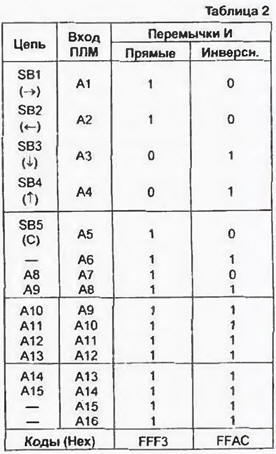
Of the 48 elements 16I available in the matrix, 30 were used. An example of preparing programming codes for an element that simulates pressing the "C" key is shown in Table. 2.
It is required to send a signal from line A8 of the data bus (input A14 PLM) to line KL3 of the keyboard port (output B4 PLM), if the buttons are "Right". "Left" and "Shoot" are pressed together. In an unprogrammed PLA, each of the inputs A1-A16 is connected to the corresponding input of the element 16I through two fusible jumpers, and in the circuit of one of them there is an inverter. If you burn the "inverse" jumper, the argument will go to the input of the AND element directly, and if the "direct" - inverted. Burning both jumpers generally excludes this argument from the implemented function. In binary digits of programming codes, jumpers to be removed are designated as logical 1. In our case, the pressed buttons of the joystick correspond to logical 0 on the PLA inputs connected to them. To implement the AND function, they must be inverted. by removing the "straight" jumpers. And in the bits associated with the buttons that are not pressed in this combination, the "inverse" ones are removed. Next, the address bus line to be used is specified. Since the active logic level on it is low, the "direct" jumper is also removed in the corresponding bit of the code, leaving the "inverse" jumper. It remains to disable unused inputs by removing both jumpers in their bits. The OR matrix consists of eight (one for each output) 48OR elements, the inputs of which are connected through jumpers to the outputs of the AND matrix. Thus, at the output of each of the 16I elements there are eight jumpers, burning through which disconnect it from the corresponding 48OR element, which means that and from the output of the PLM. Output B1 corresponds to the least significant, and B8 - the most significant digit of the programming code. To leave the connection we need with the output B4, set the code 0F7H. If a mistake was made during programming or it became necessary to replace one function with another, all jumpers are burned out (code 0FFH). completely disconnecting the unnecessary element AND from the outputs. Instead, one of the remaining unused programs is programmed. As long as there are such elements, the operation can be repeated repeatedly, improving and supplementing the joystick operation algorithm. Note that the Left button simulates pressing the 5 key, regardless of the state of the Up button. Similarly, the "Up" button simulates pressing the "7" key, regardless of the state of the "Left" button. Therefore, the simultaneous pressing of these buttons for the computer is equivalent to the same pressing of the mentioned keys. This also applies to the "Down" and "Right" buttons, which mimic the "6" and "8" keys. The key combination "0" and "5" required two AND and OR elements. This is necessary so that the A0 signal does not enter the KL11 circuit, and the A4 signal does not enter the KL12 circuit. It is easy to see that when the specified keys are pressed, the unspecified ones are free, and the selected address bus line has a logical 0. At the PLA output, instead of the required logical 0, 1 will appear. However, it is possible to invert the output signals by burning the jumpers of the NOT matrix. In our case, this must be done by deleting them all. Similarly, you can program the PLA to work with a joystick that has normally closed contacts. If necessary, it can be used to connect a keyboard to the computer, the internal connections between the keys of which do not correspond to the "standard" ZX-Spectrum (for example, the keyboard "Electronics MS 7007"). Using the advanced features of the joystick, you should keep in mind that sometimes, together with the desired key, it simulates pressing several others. This is due to the fact that it is impossible to press all the necessary buttons at the same time, and all intermediate states that briefly occur in the process of typing a combination can be perceived as pressing the corresponding keys. Fortunately, many game programs do not respond to this. If you cannot enter the required character in any way, try pressing the buttons in the desired combination with the SA1 switch open. Then, while holding them, close the switch. Literature
Author: V.Solonin, Konotop, Ukraine
Alcohol content of warm beer
07.05.2024 Major risk factor for gambling addiction
07.05.2024 Traffic noise delays the growth of chicks
06.05.2024
▪ A battery that generates electricity from human sweat ▪ Found a link between fear and alcohol addiction
▪ site section Electrician's tool. Article selection ▪ article There are women in Russian villages. Popular expression ▪ How long does it take for a person's nails and hair to grow after death? Detailed answer ▪ article Mariannik oak. Legends, cultivation, methods of application ▪ article Fountain from a vase and a hand. Focus secret
Home page | Library | Articles | Website map | Site Reviews
www.diagram.com.ua |


 Leave your comment on this article: