|
|
ENCYCLOPEDIA OF RADIO ELECTRONICS AND ELECTRICAL ENGINEERING The use of ultrasound. Encyclopedia of radio electronics and electrical engineering
Encyclopedia of radio electronics and electrical engineering / Electronics in everyday life The use of ultrasound is another direction in the development of Proximity Detectors. Figure 1 shows how such a device works. The upper part of the figure shows a possible configuration when the transmitter and receiver of the ultrasound are opposite each other. As long as nothing prevents the ultrasound from fully reaching the receiver, the circuit is on hold. And just the intruder, located between the emitter and the receiver, can prevent this.
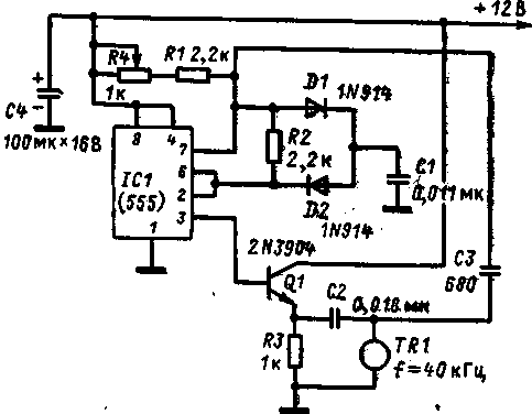
Such a device can provide a very high level of reliability. After all, any decrease in the signal level from the transmitter or even the termination of its operation in general will be regarded by the receiver circuits as a danger. The above examples may occur simply when the transmitter is disabled. The bottom of the figure shows another effective receiver and transmitter arrangement. In this case, the ultrasound is reflected from a solid object at a distance and arrives at the receiver. The signal emitted by the transmitter must be strong enough. Naturally, any object that gets in the way of the sound will trigger an alarm. Another way of operating the device is possible. In this case, the sound reaches the receiver only by bouncing off the burglar in the vicinity of the transmitter and receiver. All of the methods described are good, so choose the one that best suits your conditions. Ultrasonic watchdog with separate receiver and transmitter Figure 1 shows a schematic diagram of an ultrasonic transmitter. It is based on a 555 type timer, and the operating frequency is determined by the values of the resistors R1 and R4 and the capacitor C1.
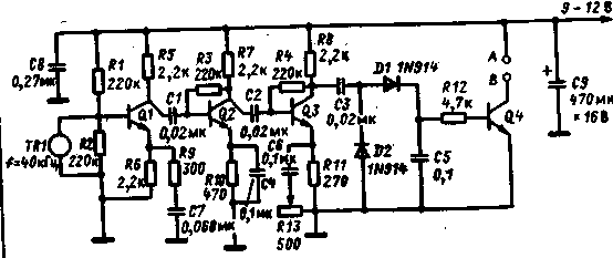
The ultrasonic transducer TR1 provides the greatest return at its own resonant frequency, which means that it must be powered at this frequency. If during operation of the device the frequency of the transmitter generator will "float", this at some point will lead to a decrease in the level of the signal emitted by the transmitter, i.e. will cause a false alarm. To increase the stability of the generator frequency, feedback is created in it through the capacitor C3. The emitter itself becomes similar to a resonant circuit, the signal on which is maximum at the resonance frequency. Thus, the induced positive feedback keeps the generator at the natural frequency of the emitter and narrows the tuning range of its resistor R4. To further increase frequency stability, power the circuit from a stabilized power supply. But I must say that supply voltage surges up to 1 V do not cause either a frequency shift or a decrease in the output signal level. The transmitter is assembled on a board of insulating material and placed in a metal or plastic case. When installing, be careful, but in general, the scheme is not critical to the arrangement of parts, and select the design at your discretion. Since there are few parts in the transmitter, it would be nice to place both the board and the emitter in one housing. In addition, long connecting wires leading to the emitter adversely affect the operation of the circuit. But if you still can’t do without wires, make them no more than 15 cm long. When all the preparatory work is completed, start setting up the transmitter. The task is to tune it to the natural frequency of the emitter. If you have an oscilloscope, connect its signal wire to the connection point of the capacitors C2 and C3, and the "ground" to the common wire of the circuit. Set the gain range switch to 1 V/div. Resistor R4 achieve a significant increase in the amplitude of the signal on the oscilloscope screen. The maximum signal shows that we have tuned in to the resonant frequency. This single operation to set up the transmitter can be postponed until the time when the receiver is ready. The receiver circuit is shown in Fig.2.
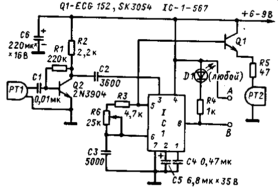
Transistors Q1, Q2 and Q3 form a well-known three-stage amplifier, the task of which is to increase the level of the received signal to a value where it can be detected, and to turn the transistor Q4 into the open state with the received constant voltage. The overall gain of the circuit is controlled by a variable resistor R13 included in the emitter circuit of transistor Q3. From the collector of this transistor, the signal goes to the rectifier with a doubling of the voltage. The DC voltage generated across capacitor C5 creates a bias at the base of transistor Q4 through resistor R12. The assembly of the receiver is practically no different from the assembly of the transmitter. As there, the wires connecting the ultrasonic sensor to the circuit should be kept as short as possible. Place the finished board in a metal or plastic case. Putting the device into operation If you follow the image at the top of Fig. 3.20, the first step in verifying the operation of the circuit should be to determine how far the receiver and transmitter can be separated. Choose a place where there are no air currents. Place the emitter of the transmitter at a height of 1 m above the floor, directing it to an open space. Apply temporary power to the receiver. Set resistor R13 to the position of the lowest resistance, which will correspond to the maximum gain. Connect a DC voltmeter to the Liv terminals. If the amplitude of the ultrasonic waves is high enough, the voltmeter will show a voltage almost equal to the supply voltage. Slowly move away with the receiver from the emitter of the transmitter. From some place, the readings of the voltmeter will begin to jump, sometimes even falling to zero. After that, reduce the distance by 30-60 cm, once again making sure that the device works reliably. When installing an ultrasonic alarm, there are a few clear guidelines to follow. 1. Do not stir it in the area where the air conditioner is operating in the blowing air mode. Otherwise, the alarm will be triggered every time it is switched. As mentioned above, it is possible to arrange the transmitter and receiver in such a way that the latter will perceive the sound reflected from any solid surface. It could be a stack or a door. Human clothing reflects poorly and, conversely, absorbs ultrasound well. When someone crosses one of the beams, the alarm will go off. If the door was armed, the device will react when it is opened. The emitter of the transmitter and the ultrasonic sensor of the receiver are located at a distance of no more than 5 cm from each other, while the device is able to "notice" a person or any object a few centimeters away from him. Wherever you install your creation, do not forget the following: do not tune to maximum sensitivity and use the device in adverse environmental conditions. Signaling device with combined receiver and transmitter The scheme of the next ultrasonic guard is shown in Fig.1. The scheme is unusual in that, on the basis of one microcircuit, it contains a transmitter generator and that it also works as a selective receiver of the reflected signal. For this, a 567 microcircuit is used, which contains a signal source and its receiver.
Let's take a closer look at how a circuit that performs double work functions. The waves are perceived by a piezoceramic sensor, after which they are amplified by a cascade on the transistor Q2, they go to pin 3 of the microcircuit, and the signal frequency is exactly equal to that generated by the microcircuit itself. Unlike the previously described device, in this situation it is no longer important how much the frequency may deviate from the originally set one. The operating frequency is determined by the values of the chain of resistors R3 and R6 and the capacitance of the capacitor C3. It is regulated by a variable resistor R6. With given ratings of parts, it can vary from 8 to 25 kHz, and ultimately is determined by the piezoelectric sensors used. From pin 5 of the microcircuit, a rectangular signal is fed to the base of transistor Q1, which is connected according to a common collector circuit. As a load of this transistor, a chain of resistor R5 and a low-resistance speaker is connected. When a signal of sufficient amplitude arrives at the input of the circuit, the LED is on, and terminals A and B are normally closed contacts. In the case when the amplitude of the signal decreases or it is completely absent, the output of the circuit goes into an open state. Otherwise, this device can be used according to any configuration proposed in Fig. 3.20. Frankly, the circuit works better at high audio frequencies than at ultrasonic ones. The last word about the operating frequency is said by the emitter and piezoelectric sensor used in the device. For those listed in the list of applicable parts, the frequency ranges from 8 to 16 kHz. If you are not satisfied with such frequencies, you just need to choose another "pair, since the circuit itself can operate at frequencies up to 25 kHz. The upper limit is limited only by the capabilities of the microcircuit. But you should not be especially zealous, since for frequencies above 43 kHz it is already difficult to select an emitter and piezoelectric sensor. Complete with two proposed converters, the circuit works very well at a frequency of 12 kHz. And it's not scary that she is heard. After all, hardly anyone dares to argue with her. And the mice, apparently, would prefer some other place than this. Circuit Assembly The parts of the circuit are mounted on a board of insulating material, and since there are not so many of them, the mounting density does not affect its operation. In this design, it is not required to place the piezoelectric sensor and the emitter in the vicinity of the circuit itself. But then it is desirable to use shielded wires for each converter. This will avoid a direct connection between the output and the input of the circuit. Putting the device into operation. After checking the correct installation, connect the circuit power. This may be a 6-9 V source. Set the slider of the resistor R6 to the middle position, and you should hear a high-pitched squeak. Install the emitter on a table or other stand so that there is a free space of 3 m in front of it. Holding the piezoelectric sensor in your hands, point it at the emitter. The LED should light up. Moving away from the emitter with the piezoelectric sensor, notice the place where the LED goes out. This means that you have found the point of maximum sensitivity. We indicate the places where it is convenient to place such an alarm: - through the room; Publication: N. Bolshakov, rf.atnn.ru
Machine for thinning flowers in gardens
02.05.2024 Advanced Infrared Microscope
02.05.2024 Air trap for insects
01.05.2024
▪ Ultra-compact electric vehicle iEV Z ▪ Mitsubishi Automotive Projection Systems
▪ section of the Garland website. Article selection ▪ article Fet Afanasy Afanasyevich. Famous aphorisms ▪ article The system of social insurance of workers in the Russian Federation ▪ article Blue lacquer for steel. Simple recipes and tips ▪ article Thermomagnetic effects. Encyclopedia of radio electronics and electrical engineering
Home page | Library | Articles | Website map | Site Reviews www.diagram.com.ua |


 Arabic
 Bengali
 Chinese
 English
 French
 German
 Hebrew
 Hindi
Hindi Italian
 Japanese
 Korean
 Malay
Malay Polish
 Portuguese
 Spanish
 Turkish
 Ukrainian
 Vietnamese


 Leave your comment on this article: