|
|


 Arabic
 Bengali
 Chinese
 English
 French
 German
 Hebrew
 Hindi
Hindi Italian
 Japanese
 Korean
 Malay
Malay Polish
 Portuguese
 Spanish
 Turkish
 Ukrainian
 Vietnamese
|
ENCYCLOPEDIA OF RADIO ELECTRONICS AND ELECTRICAL ENGINEERING FM receiver 400-450 MHz. Encyclopedia of radio electronics and electrical engineering
Encyclopedia of radio electronics and electrical engineering / radio reception The receiver is built according to the superheterodyne circuit with double frequency conversion. It is designed to receive narrowband FM in the range of 400 - 450 MHz. The sensitivity is about 0,5 μV. The purpose of its creation is to "capture" as much as possible the frequencies for which SAW resonators of the 4XX MHz range are produced by the industry. However, the tuning limits may be different (see the datasheet for the midrange used in the design). The scheme is classical and has no features.
The first IF is 45 MHz (selected when programming the controller). The second is 455 kHz. The minimum frequency tuning step is 5 kHz, the maximum is 1 MHz (selected when programming the controller). The minimum and maximum frequency tuning limits (400 - 450 MHz) are also set at the controller programming stage. Despite the fact that the tuning limits are quite wide, the noise of the synthesizer is almost imperceptible. True, for this I had to select the values of the loop filter of the midrange and the brand of the varicap quite carefully. The receiver local oscillator frequency is lower than the received signal frequency by the IF value (selected when programming the controller). The display shows the frequency and level of the received signal, as well as the battery level. The current consumed by the receiver at medium volume (ULF loaded on headphones 30 Ohm) is about 50 mA (with the backlight off). Setting Tuning the receiver comes down mainly to "fitting" the tuning range of the midrange into the desired frame. In this case, special attention must be paid to ensure that the voltage on the varicap remains with a "margin" of approximately 0,7 volts at the lowest frequency and at the highest frequency. That is, it should be achieved by expanding the turns of the local oscillator circuit so that at the lower frequency limit, the voltage on the varicap (it is convenient to measure it without interfering with its setting on the loop filter capacitances) would be 0,7 V, and at the upper limit about 3 V. If the entire midrange unit power from a separate 7805 regulator (which is better than a simple decoupling consisting of a 100 ohm resistor and a large capacitor, as in the diagram), then the voltage at the highest tuning frequency can be 4-4,5 V. Shielding of the midrange unit is essential In the photo, the midrange block is still without the top cover. Attention! In the process of tuning the midrange, the 100 kΩ resistor through which the tuning voltage is applied to the varicap was replaced by 1 kΩ (corrected in the circuit and the board), which favorably affected the noise characteristics of the midrange. The photo was taken before it was replaced.
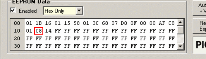
Details For the most part, they are soldered from end-of-life radiotelephones. Including 455nd IF filter and discriminator at XNUMX kHz. The 45 MHz filter is taken out of the NMT mobile phone. The mixer load can be either a resistor (in the diagram) or a resonant circuit (in the photo). At low IFs of 10,7 and 21,4, there was no particular difference, at 45 MHz IF the best results are with the circuit. However, it is more convenient to pre-adjust with a resistor, since a mixer loaded on the circuit can self-excite and mislead. The SMD circuit consists of 15 turns, the capacitance parallel to it is 56 pF. The inductance was not measured - the first one that came to hand was taken with the number of turns, more or less plausible for a frequency of 45 MHz. Quartz at a frequency of 44,560 MHz can be replaced by 14 MHz, since it is still harmonic. An indicator of any 2 lines of 16 characters each based on the HD44780 controller. Possible nuances are the mismatch of the outputs with those used in this design. You may need to turn on pin 3 through a voltage divider to set the optimal contrast level (see datasheet for indicators based on HD44780). The display used in this design has an optimal contrast level when the 3 output is at ground. Battery level indicator power supply has 5 levels. Lowest level at 7 volts (battery dead). Highest level at 8,2 volts (battery charged). Adjusted by "Battery Level Detector" resistors if needed. Mounting is made on boards made of double-sided fiberglass. The reverse sides of the boards are a common bus. EEPROM When programming the controller, the main settings for the correct operation of the device are entered into its memory. 01 1B 16 - the last local oscillator frequency of the receiver, excluding the IF, to which it was tuned before turning off the power. These figures will change during operation. The next time the receiver is powered on, the local oscillator will be set to the same frequency.
It is calculated as follows Let's say the set limits for tuning the receiver are 400 - 450 MHz. The local oscillator tuning limits without taking into account the IF will be as follows. Lower 400 - 45 = 355 MHz. Upper 450 - 45 = 405 MHz. Therefore, the local oscillator frequency settings in the first three memory cells should not go beyond these limits. 01 1B 16 corresponds to the frequency displayed on the display 407,350 MHz and the real frequency of the local oscillator 407,350 - IF (45) = 362, 350. To calculate the value stored in memory, the local oscillator frequency should be divided by a step. 362,350 (MHz) : 0,005 (MHz) = 72470 (Dec) or 01 1B 16 (Hex). On an engineering calculator, the number will look like 1 1B 16. Enter 0 in the empty high order. The next three cells are occupied by the number 01 15 58.
It is a lower local oscillator frequency tuning limit. These settings correspond to an actual local oscillator frequency of 355 MHz (the frequency shown on the display will be 400 MHz as the IF is added). Calculated in the same way... 355 (MHz) : 0,005 (MHz) = 71000 (Dec) or 01 15 58 (Hex). Installation the upper the local oscillator tuning limit occupies the following three addresses.
This is a three byte number 01 3С 68, which corresponds to a real frequency of 405 MHz (the display will show 450 MHz, since the IF will be added - 45 MHz)
405 (MHz) : 0,005 (MHz) = 81000 (Dec) or 01 3C 68 (hex). Next is a two-byte number 07 D0.
This is the coefficient for the receiver's reference oscillator. The quartz resonator used in this case, at a frequency of 10 MHz. The ratio is calculated by dividing the reference oscillator frequency by the step. 10 (MHz) : 0,005 (MHz) = 2000 (Dec) or 07 D0(Hex). next two bytes 0F 00 - optional midrange settings.
They don't need to be changed. The last three bytes of the top line number 00 AF-C8 is the IF (45 MHz).
00 AF C8 (Hex) or 45000 (Dec). Accordingly, if the IF is planned for example 10,7 MHz, then the number will be 00 29 SS (Hex) which is 10700 in decimal form. First byte of the second line 01. This is the sign of the PC.
01 means the IF is added to the local oscillator frequency to display on the display. If you write 00 into the cell, then the IF will be subtracted from the local oscillator frequency. С8 - maximum frequency tuning step.
If, by pressing the encoder shaft, turn it 1 step, then the receiver will rebuild 200 steps at once C8 (Nex) or 200 (December) which corresponds to 1 MHz. The last digit written to the controller's memory during programming is the zero correction for the S meter.
The fact is that even in the absence of a signal, there is still a noise voltage at the corresponding output of the IF chip, this leads to “waste” readings of the Smeter. The readings could be corrected with a voltage divider, but this method would adversely affect the scale and accuracy of the readings. Yes, and the UPC can be assembled on a different microcircuit, which differs in parameters from TA 31136. The correction value "shifts" the scale to the left beyond the "display limits" by as many divisions as it is written in the cell. In this device instance, this is 14 (Hex) or 20 (Dec). Download Lay PCB and HEX Firmware Author: Sergey (blaze), Kremenchug, blaze2006@ukr.net, tel. 8-050-942-35-95; Publication: cxem.net
Artificial leather for touch emulation
15.04.2024 Petgugu Global cat litter
15.04.2024 The attractiveness of caring men
14.04.2024
▪ Transcend USB 3.0 Flash Drives 128GB and 256GB ▪ HP EliteOne 800 AiO G5 Anti-peeping All-in-One PC ▪ Sensory Compensation Mechanism ▪ Xiaomi USB-C Multi-Function Adapter
▪ section of the Antenna website. Article selection ▪ article Who Invented the Parachute? Detailed answer ▪ article Kuril Islands. Nature miracle ▪ article What is wind energy? Encyclopedia of radio electronics and electrical engineering
Home page | Library | Articles | Website map | Site Reviews
www.diagram.com.ua |


 Leave your comment on this article: