|
|


 Arabic
 Bengali
 Chinese
 English
 French
 German
 Hebrew
 Hindi
Hindi Italian
 Japanese
 Korean
 Malay
Malay Polish
 Portuguese
 Spanish
 Turkish
 Ukrainian
 Vietnamese
|
ENCYCLOPEDIA OF RADIO ELECTRONICS AND ELECTRICAL ENGINEERING Radio station at 420 ... 435 MHz. Encyclopedia of radio electronics and electrical engineering
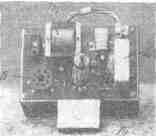
Encyclopedia of radio electronics and electrical engineering / Civil radio communications Scheme and design The described radio station at 420-435 MHz (Fig. 1) is made according to the transceiver scheme. Its features are the simplicity of the scheme and design, reliability in operation, efficiency and the use of printed wiring. The power supplied to the anode circuit of the generator does not exceed 3-4 W (current 25 mA at an anode voltage of 150 V). The sensitivity of the receiver is not worse than 5-10 microvolts.
The radio station was operated without changing lamps for two years and showed good results both in the conditions of Gorky and in the field. Schematic diagram of the radio station is shown in fig. 2. In the high-frequency part, the L1 6N15P lamp is used. In receive mode, it operates as a push-pull super-regenerator. The same lamp, together with the circuit L3, L4, C4, is a damping frequency generator; the latter is chosen to be 465 kHz, but may lie in the range of 0,4-4 MHz.
The phones are directly connected to the anode circuit of the L1 lamp, which ensures sufficient volume even when receiving distant correspondents. Potentiometer R6 allows you to set the required super-regeneration mode. When receiving, the L2 lamp is not used, however, to simplify switching, the anode voltage is not removed from it. In transmission mode, the L1 lamp operates as a self-excited push-pull generator. Feedback is provided by the interelectrode capacitances of the lamp and the mounting capacitance. The transmitter uses anode modulation. The modulator is assembled on an L2 lamp, a carbon microphone is connected to its input through a microphone transformer. The latter is powered by a constant voltage taken from the cathode resistance R5. Communication with the antenna is inductive (communication loop L1). Tuning the radio station in frequency is carried out by moving the short-circuit jumper along the two-wire line L2. Setting with a capacitance or a flag is impractical due to a sharp decrease in the quality factor of the line and a decrease in the generator power. Design Structurally, the radio station is made in the form of two blocks: an RF block and a modulator. The first block is placed in a metal case measuring 143X90X70 mm, the second is made on a printed circuit board (140x90 mm), which is attached to the first block and connected to it using a connector. On the printed circuit board, made by etching foil getinax, there are sockets for turning on the microphone, a microphone transformer Tp1, a chip for connecting the power cable, a lamp L2, a modulating inductor Dr1, resistances R2, R3, R4, R5, capacitors C1 and C2 (Fig. 3 ).
In the block, assembled on the corner chassis, all other parts are placed (Fig. 4). The two-wire line L2 is located on a polystyrene plate attached to a vertical partition. The front panel has a connector for connecting an antenna feeder, a screw with an insulated knob for setting the line, a resistance knob R6, jacks for turning on telephones, a connector for a chip from a modulator and a switch for the type of operation P1.
The use of printed wiring is not mandatory, however, the conductors connecting the ends of the L2 line to the anodes of the L1 lamp must be of a minimum length. The microphone transformer Tp1 is wound on a core with a cross section of 1,5-2 cm2. The primary winding I contains 400 turns of PE 0,3 wire, the secondary - II-8000 turns of PE 0,08 wire. As a modulation choke, the filter choke of the Ural radio receiver was used (contains 3000 turns of PEL-0,15 wire), the inductance is not less than 4 H. The circuit of the quenching frequency generator L4C4 is the circuit of the IF of the Baltika receiver. The L4 circuit coil consists of two sections of 142 turns of LESHO 7x0,07 wire, wound on a polystyrene frame with a diameter of 8,6 mm. Winding type "Universal". It is possible to use any other IF circuit, the resonant frequency of which lies in the range of 0,4-4,0 MHz. The feedback coil L3 has 30 turns of PESHO 0,15 wire and is wound between two sections of the L4 coil. Chokes Dr2 , Dr3, Dr4 and Dr5 frameless with an inner diameter of 5 mm, made of silver-plated wire with a diameter of 0,8 mm and contain 6 turns each. The main part of the radio station is a two-wire line L2, the design of which is shown in fig. 5. The quality of the station operation depends on the thoroughness of its manufacture.
The line is made of copper, bronze, brass. Tubes and contacts made of foil 0,3-0,5 mm thick must be silver-plated. The assembly order of the line is as follows. Two tubes 1 are inserted in parallel into the base 2 and soldered. Contacts 3 are rolled up into a tube, inserted into the holes on jumper 4 and also soldered. A screw is inserted into the jumper hole (2 mm in diameter), and its protruding end is riveted. Next, the jumper is put on the tubes, screw 5 is screwed into the base. The rubbing parts of the screw are lubricated, but the tubes cannot be lubricated. The jumper should move smoothly, without distortion. At the base of the line there are two threaded holes for fastening to the insulator. The communication loop L1 is made of silver-plated copper wire with a diameter of 2 mm. The distance between the line and the communication loop is selected when establishing the station. Radio Power To power the radio requires a voltage of 150-170 V (current 35-40 mA in transmit mode and 17 mA in receive mode). The filament voltage is 6,3 V at a current of 0,9 A. In stationary conditions, power is supplied from a conventional rectifier. In the field, a battery is used for heating, and two series-connected BAS-80 batteries are used to power the anode circuits. Antenna The radio station can work with wave channel (4 elements) or double square antennas. The latter is structurally simpler. Setting up a radio station A properly assembled radio station immediately starts working. In the absence of over-regeneration, it is necessary to switch the ends of the feedback coil L3. Having obtained a stable super-regeneration, the frequency overlap is checked. Then an antenna is connected to the radio station. In this case, the oscillations of the super-regenerator can break, which indicates a strong connection of the circuit with the antenna. By changing the distance between the L1 connection loop and the L2 line, they ensure that the generation does not break down in the entire frequency range, while simultaneously monitoring it. so that the transmitter power is not too reduced. In the receive mode, a weak coupling of the antenna with the loop is required, in the transmit mode, a stronger one. Therefore, when establishing, it is necessary to provide some kind of optimal connection. The establishment of the radio station transmitter consists in such a selection of Dr2, Dr3, Dr4, Dr5 to ensure maximum generator power. The modulator does not require special adjustment, only the quality and depth of modulation are checked. The final tuning of the radio station should be carried out in the field, using the simplest field strength indicator, as well as when conducting two-way communications. Author: G. Belevich (RA3TCF); Publication: N. Bolshakov, rf.atnn.ru
A New Way to Control and Manipulate Optical Signals
05.05.2024 Primium Seneca keyboard
05.05.2024 The world's tallest astronomical observatory opened
04.05.2024
▪ The cosmic wind stretched over 228 light-years ▪ ASUS PadFone E smartphone tablet ▪ YouOn Hydrogen Electric Bike
▪ site section Power supplies. Article selection ▪ article by Paul Henri Holbach. Famous aphorisms ▪ What animal children are four times the size of their parents? Detailed answer ▪ article Sail on a rubber boat. Personal transport ▪ article Electrical stimulator for fish. Encyclopedia of radio electronics and electrical engineering
Home page | Library | Articles | Website map | Site Reviews
www.diagram.com.ua |


 Leave your comment on this article: