|
|


 Arabic
 Bengali
 Chinese
 English
 French
 German
 Hebrew
 Hindi
Hindi Italian
 Japanese
 Korean
 Malay
Malay Polish
 Portuguese
 Spanish
 Turkish
 Ukrainian
 Vietnamese
|
ENCYCLOPEDIA OF RADIO ELECTRONICS AND ELECTRICAL ENGINEERING Radio interference suppressor. Encyclopedia of radio electronics and electrical engineering
Encyclopedia of radio electronics and electrical engineering / Civil radio communications The worsening interference situation on the amateur bands every day requires shortwave operators to take effective measures to combat interference. It is far from always possible for a radio amateur to eliminate interference in places where they occur. The problem has to be solved by improving the equipment and antenna devices at the reception point. An effective way to eliminate certain types of interference is proposed in this article. Principle of operation The device described in this article is installed at the input of the receiver. It is designed to suppress radio interference coming from a certain azimuth, which the operator can arbitrarily set at any frequency in the frequency band from 1,8 to 30 MHz. Even a very high-class receiver is helpless if powerful radio interference "covers" the useful signal. To some extent, a directional antenna, which has spatial selectivity, can solve this problem. If the interference and the useful signal do not come from the same direction, then by deploying the antenna with a minimum radiation pattern (DN) to the source of the interference, it is possible to improve the signal-to-interference ratio (S/I). A well-designed antenna has a back/forward ratio (F/B) of 30...40 dB. Of course, not all radio interference problems can be solved using the spatial selectivity of the antenna system. First, it is impossible, as already noted, if the useful signal and interference come from the same direction. Secondly, if the interference comes from all directions. And finally, using traditional directional antennas to suppress interference is unrealistic on low-frequency amateur bands. But interference coming from all directions is rare. Much more often they are localized in azimuth. Their source may be:
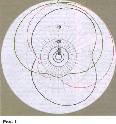
In these cases, if the azimuth of the desired signal differs from the azimuth of the interference by at least a few degrees, the device discussed in the article can improve the S / R ratio. Depending on the specific situation, this improvement ranges from a few to 30...40 dB. Even if you have a directional rotating antenna, it will be useful to you. It is unlikely that your antenna has the ability to change the elevation angle, and when suppressing local interference, a minimum of RP at a certain zenith angle may very well be required. And certainly it does not have a uniform F / B ratio over the entire operating frequency band (at its edges, as a rule, it decreases). So how to implement a receiving directional antenna with the ability to rotate the minimum of its RP? Antenna systems come to the rescue, consisting of two antennas, the signals of which are processed by passive and active circuits, and then summed up. Let there be two different antennas located at some (not closer than 0,05A.) distance from each other. It is clear that the same electromagnetic wave will induce different RF currents in both antennas. The phase difference of these currents will be determined both by the distance between the antennas and by the azimuth angle of signal arrival. The difference in amplitudes is the size of the antennas and their relative position. Let the phase difference of the interference signals at the outputs of both antennas be Δφ1, and the amplitudes be different. Let's equalize the signals from each of the antennas in amplitude, for example, by including an attenuator in the cable with a stronger signal, and shift the phase of one of the signals by Δφ = 180 - Δφ1. Then the total phase shift will be exactly 180 degrees. Obviously, if we now add both signals, then the sum will be zero (two antiphase signals of the same amplitude). This "zero" (or rather, not zero, but some minimum) is very narrow and deep. Anyone who has ever set up a balanced circuit to suppress a signal (for example, a balanced modulator) will understand what is at stake. The depth of the minimum depends on the accuracy of the amplitude equalization and the exact antiphase of the added signals and can reach 40..60 dB. And even large values with a good adder, excluding the direct passage of the signal. This is how you can reduce the interference. But how will the useful signal change? If the azimuth of its arrival is different from the azimuth of the interference, then the phase difference of the useful signal induced in both antennas will no longer be Δφ1, but some other one, say, Δφ2. The significance of this fact is very great, because the sum Δφ + Δφ2 will no longer be equal to 180 degrees. That is, the useful signals at the adder, not being exactly anti-phase, will be attenuated much less than the interference. Deviation from the exact antiphase of the signals even by a few degrees reduces the signal attenuation by 15...20 dB. And that is how the S/P ratio at the output of the adder increases. If the phase shift Δφ1 differs significantly from Δφ2 (by tens of degrees), then the useful signal is practically not attenuated and the improvement in S/P reaches 40...60 dB. If Δφ1 differs from Δφ2 by 180 degrees (even not very accurately, here a difference of 20 ... 60 degrees is acceptable), then the useful signal at the adder output almost doubles (it is added in phase when received by both antennas). This gives an additional 6 dB improvement in S/P ratio. "It's all good, but I don't have a second antenna for each band. And it's not expected. What then?" the reader will ask. The matter is greatly simplified by that. that we need a receiving antenna, and therefore, its degree of coordination with the feeder and efficiency are not of decisive importance. For this reason, an antenna of a different band and/or a separate receive antenna can advantageously be used as the second antenna. You can generally use just two receiving antennas. To process signals from antennas, we need a two-channel adder with the ability to control the amplitude in both channels (who knows which of the antennas will have a larger signal) and a 360-degree phase in one of the channels (since we are talking about a difference, it is enough to adjust it in one). That is, just something to do: two attenuators, one phase shifter and one adder. There are many such devices (under different names). The MFJ-1026 and ANC-4 are commercially available. And this is only what I managed to remember, but in reality - much more. What can be achieved with their help? With a well-made device, everything depends on the antennas and their relative position. On fig. 1 shows the radiation patterns obtained in the MMANA antenna modeling program. Range - 80 meters. Two antennas were used - the main Inverted V on a mast 15 m high and an additional receiving frame with a side of 1 m, located vertically. Distance between antennas - 20 m.
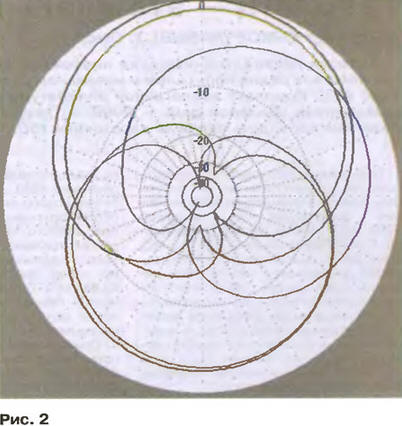
Not all possible RPs are shown, but only a part of them, related to the sector 0...90 degrees (for the sector 90..360 degrees, exactly the same, but rotated RPs are obtained by rotation). It can be seen that at angles of 310...50 and 130...230 degrees it is possible to obtain a significant (up to 20 dB) improvement in the S/P ratio. For angles of 50..130 and 230...310 degrees, the improvement is much smaller - a few dB. Although a few dB are not lying on the road (in some cases it is a question whether the QSO will take place or not), it is still better to use another additional antenna for these angles, located at an angle of 90 degrees relative to the first frame. On fig. 2 shows RPs in the range of 160 meters with phasing of a shortened vertical with capacitive loads and a separate receiving vertical frame similar to the first example. Distance between antennas - 20 m.
Here I have given more RPs to demonstrate within what limits the position of the minimum can be changed (and it reaches 30...40 dB). In principle, the trend is similar to the previous case - for sectors 310...50 and 130...230 degrees, very deep suppression can be achieved. For the rest of the semicircle (that is, 50..130 and 230...310 degrees) it would be better to use a different additional frame. It should be noted that the interference suppression (minima) in the two figures above characterizes not the quality of the phasing device (it is assumed to be good), but the properties of the data, specific two-element active systems. With other antennas and their other location, the suppression can be either greater or less. It is desirable that phased antennas be polarized matched. An attempt to phase the dipole and the vertical will not give a good result. Although it also depends on the height of the antennas above the ground - after all, the dipole also has radiation with vertical polarization. It is important to note that the second antenna should not be a piece of wire lying on the table. It should be a full-fledged receiving antenna, and not a "noise" antenna, as it is sometimes called. The recommendations (although they even penetrated the manuals for the mentioned devices) are completely irresponsible recommendations to place a telescopic pin or wire near the source of interference (say, TV or computer). Such a pin, in addition to the interference that pesters the main antenna (which can be phased and suppressed), will additionally receive a bunch of various household "garbage" (pickup from networks, etc.) that cannot be suppressed. Simply because the main antenna "does not hear" them. As a result, the received signal will be "enriched" with any "garbage" received by the telescopic antenna. It looks as if the source of interference with which we are fighting is considerably weakening (we are phasing its signals), but on the other hand, a lot of "garbage" that was absent before appears. It is much better to deal with interference sources at home by directly eliminating their radiation (isolation filters, case grounding, etc.). That is why the second antenna, although it may be small and inconsistent, should be located not far from the main antenna - in a place where it will not collect additional interference. The minimum distance between antennas is 0,05λ. Too short a distance results in a narrow bandwidth in which interference is suppressed, and it becomes necessary to adjust the phase shift in the device when the operating frequency changes. A very large distance between the antennas, contrary to popular belief, does not lead to an improvement in the suppression parameters (but does not worsen them either). The optimal distance from all points of view will be in the range from 0,1 to 0,5λ. When modeling such a two-element system in MMANA, you need to install two sources (one in each antenna), manually apply a much higher voltage to the smaller antenna (say 10 V) and optimize the amplitude and phase of the smaller source (connected to the larger antenna) according to the criterion F/B. Moreover, for a source with a small amplitude, you must manually set a very small voltage change step (something like 0,0001 V). To obtain suppression in the desired direction, rotate the entire antenna system in MMANA ("Edit - Rotate - Z") in azimuth so that the desired direction coincides with 180 degrees. This requirement is MM AN A - the F/B ratio is calculated in the program along the 0-180 degree line. Scheme of the device and the results obtained So, we need a two-channel adder with independent amplitude control in each channel and a controlled phase shifter in one of them. By setting the amplitudes and changing the phase shift, we will manually solve the problem of creating a unidirectional antenna system from the available pair of antennas with a minimum in the required direction. What are the requirements for such a device?
Let's see how these requirements are met in known designs. A simple yet good design was developed by JA1DI [1]. It uses a phase shifter on the KPI and a potentiometer, which provides small changes in amplitude when varying the phase. The ability to change both C and R for each frequency provides a small (about 6 dB) attenuation in the phase shifter. To compensate for this attenuation, a high-linear field-effect transistor stage with a small (about 10 dB) gain is used. It is this unit (phase shifter with amplifier) in this design that is made very well and thoughtfully. What, unfortunately, cannot be said about the second channel and the adder - they are made simply as resistive attenuators. Not only do they introduce high attenuation, but they also have very low channel-to-channel isolation. This necessitates the use of a full size auxiliary antenna and reduces interference suppression. An expensive (about $180) MFJ-1026 device is produced in the USA [2]. In my opinion, the circuit solutions of the MFJ-1026 are frankly weak. Here are the main miscalculations of its creators. The device uses an active adder on the differential stage. With all the linearity of the used field-effect transistors (J310), this does not add dynamic range to the receiver. Against. Recall that we are talking about antenna circuits before any filtering. The adder on two transistors of the creator of the device seemed not enough, and for its further "decoration" an emitter follower was introduced at the output. It will not add linearity to the device either. But why put it at all? After all, the J310 transistor through a broadband transformer works great for a load of 50 ohms. Phase rotation by 180 degrees jump is carried out by another cascade using a transistor. The phase shifter in the MFJ-1026 is very similar in design to what was used by JA1DI, but significantly worse than the Japanese one. In it, instead of KPI, a switch of fixed capacitors is installed. This is half the trouble. The trouble is that this switch has only two positions, and this is not enough for a complete phase rotation in the entire frequency range of the device. Rather, a full turn of 180 degrees (another 180 degrees will give the switch 0/180) is still possible, but at some frequencies the phase shifter gain drops significantly (up to -20 dB). To reduce the unevenness, I had to use a low-resistance load (two 51 Ohm resistors). As a result, acceptable amplitude non-uniformity is achieved, but at the cost of reducing the transmission coefficient. As a consequence of this circuit design, another amplifying stage was required to compensate for these losses. As a result, it turns out that even when using two full-size antennas, the signals pass through at least 5 (!) transistors. This is without any filtering, even without bandpass filters. This means that all powerful broadcasting and service stations in the entire range from 1,8 to 30 MHz will modulate each other on five (!) transistors. It is clear that even with their very good linearity, this cannot end in anything good. In my conditions, a TV transmitting center (MB and UHF) and several broadcasting stations (MW and KB bands) are located a few kilometers on the mountain. It was from the poorly debugged transmitter of this center that I had to flee. The 9...30 MHz band in my receiver is blocked by S9...9+40 dB noise (and they also say that everything is in order in Germany!). Testing the MFJ-1026 under these conditions confirmed the above. In addition to the constant direct detection of a powerful "broadcaster", in the 49 meters range in the evening, a lot of "unaccounted" signals were added, which disappeared when the device was turned off. It would be wrong to say that everything is bad in the MFJ-1026. Individual nodes are solved successfully there:
Since it was not possible to find a ready-made scheme that suited the author, I had to combine my own (Fig. 3). It does not contain any discoveries, but it is made soundly. The device is designed to work in the receiving antenna circuit of the transceiver (i.e., the transceiver must have a separate RX input), and therefore RX / TX switching is not provided. If your device has only a common antenna input, then you will have to introduce RX / TX switching into the device, forcibly turning it off in transmit mode.
Here are the main features of this device. The operating frequency band is 1,8 ... 30 MHz. The gain in this frequency band is 1, and the phase can be rotated within ±180 degrees. Interference attenuation can exceed 60 dB. The dynamic range for intermodulation with UHF turned off in the second antenna circuit is at least 110 dB. Input and output resistance of the device - 50 Ohm. Switch SA1 turns on the device. In the off state, the signal from the main antenna (connected to the XP2 connector) goes directly to the output of the device. With the introduction of RX / TX switching, the SA1 switch must be replaced by a relay that, in transmission mode, will bypass the device. The signals from both antennas first follow identical paths: overload protection circuit - attenuator - HPF. The protection consists of small-sized incandescent bulbs VL1, VL2 (6,3 ... 13 V, 0,1..0,2 A) and diode limiters VD1-VD8. The threshold for opening the limiters is about 1 V (i.e., at least 120 dB higher than the sensitivity of most KB receivers), so they do not degrade the real dynamic range. Lamps VL1 and VL2 in the cold state have a resistance of several ohms and practically do not attenuate the signal. But during transmission, if the receiving antenna is not far from the transmitting one, then the filaments of the lamps will glow, and their resistance will increase sharply. Such protection successfully copes with the functions assigned to it under the following conditions: one kilowatt per transmission in the main antenna and an auxiliary antenna 13 m long, 3 ... 5 m from the main one. I note that on some ranges the protective lamp glows with full heat. I used television attenuators (the idea of I4JMY), bought cheaply at the "flea market". In principle, you can use 50/50 Ohm smooth attenuators from a set of any measuring instruments. In an extreme case, here you can use variable resistors of group B and a resistance of 510 ... 680 Ohms, included with a conventional level controller. In the latter case, when adjusting the attenuation, the input impedance of the device will change, and if the antenna used is sensitive to this, then in addition to the amplitude, the phase will also rotate. This will complicate (although not much) work with the device. HPF taken from MFJ-1026. The installation of such a high-pass filter is justified only if the device will be used in the entire frequency band of 1,8 ... 30 MHz. If it is supposed to use the device only in a few frequency bands (bands), then it makes a lot of sense to install a band-pass filter with the appropriate bandwidth or even several switchable filters instead of the HPF. Next, the signal from the first antenna is fed to the controlled phase shifter. Switching 0/180 degrees is implemented by reversing (switch SA3) the input winding of the phase splitting transformer T1. Elements C7-C15, SA4, R1 are a smooth phase shifter borrowed from the JA1DI circuit. Only instead of KPI, a nine-position switch and a set of fixed capacitors are installed. This allowed us to solve two problems at once: to obtain a minimum parasitic capacitance per case and a large capacitance overlap. With KPI, this would not be so easy. You should not refer to the SA4 switch as a range switch - and on the 28 MHz band you may need a capacitance of 270 pF, and on the 1,8 MHz band you sometimes need a capacitance of 1 pF. It all depends on the relative position and type of antennas, as well as on the direction of interference. The amplifier on the transistor VT2 with a small margin compensates for losses in the phase shifter. Lowering T2 provides a low output impedance of the stage - 100 ohms (so much is required for the adder) - without introducing an emitter follower into the device. The linearity of this amplifier determines the dynamic range of the entire instrument. This is the only active element in the main (containing the phase shifter) path of the device. The remaining elements are passive and cannot worsen it. Transformer T4 and resistor R6 is a classic adder with high isolation between inputs. With over 40 dB isolation between inputs, it introduces virtually no loss. The only inconvenience is the input impedance of the adder (100 ohms each). If it is not difficult to get 2 ohms from the output of the transformer T100, then at the second input, in order to match the 50 ohm path, it was necessary to install a T5 transformer for the 50/100 ohm transition. In the lower position of the switch SA2 according to the diagram, a signal from the auxiliary antenna is supplied to the input of the transformer T5. If a shortened or highly mismatched antenna is used, then you may have to turn on an additional amplifier on the VT1 transistor. In this version, its input impedance is about 300 ohms (it turned out to be better for my shortened receiving antennas), voltage gain is 15 dB, output impedance is 50 ohms. In principle, this amplifier can be anything. This is determined by the characteristics of the auxiliary antenna. There is a lot of room for creativity here. Almost any linear UHF that comes with the small receiving antennas can be used. However, UHF linearity should be no worse than that of the receiver being used. Otherwise, the overall dynamic range will decrease. Just do not attribute this reduction to the described version of the device. UHF to a small auxiliary antenna is required in any case. And the problems of its overload have nothing to do with signal phasing. Since the device is installed at the input of the receiver, in order not to receive additional interference, it must be placed in a well-shielded case. It can be made, for example, from foil fiberglass. Despite the simple layout, the case must be rather big: at least seven controls are located on the front panel, and four of them (R1, SA4 and both attenuators) must be equipped with well-read scales. The following arrangement of controls is convenient:
If you have several antennas that can be used as auxiliary antennas (this is desirable, based on the data shown in Fig. 1 and 2), then put the auxiliary antenna selection switch at the input of the upper (according to the diagram) channel. They also need to be controlled on the front panel, and the corresponding number of input connectors should be installed on the back. A large number of variable resistors and switches make it easy to mount the entire device by surface mounting, while respecting the usual requirements for RF technology. Device details are also selected from these requirements. The variable resistor R1 must be non-inductive, group A. The inductors L2 - L3 can be of any type. The inductance of the inductor L1 is not critical. All transformers are wound on FT50-37 ring magnetic cores (can be replaced with K12x7x5 from 600NN ferrite). Transformers T1 and T2 contain 3x10 turns of PEV-2 wire with a diameter of 0,3 mm, transformer T4 - 2x10 turns, transformer T5 - (5 + 5) and 10 turns, transformer TZ - 1,5 (I), 10 (II) and 8 (III) turns. To improve the linearity of the device, the drain current of the transistor VT2 is chosen relatively large (25 ... 40 mA), and it is desirable to provide this transistor with a small heat sink. The device can be powered from the transceiver (current consumption - about 100 mA). Transistor VT1 can be replaced with KT610A, and VT2 - with 2SK125 or two KP307G transistors connected in parallel. If the installation is done correctly and nothing is confused in the phasing of the transformer windings, then the device works immediately and does not need to be adjusted. Therefore, we will immediately proceed to work with the device, i.e., to phasing the signals of two receiving antennas. 1. We select a range where there is a stable interfering noise or signal. Interference from a station adjacent in frequency cannot be used here. You can navigate, for example, to the AM carrier of a broadcasting station. If the tuning is in a laboratory where there are no antennas, then the same signal from the generator can be fed through the tee to both inputs at once. In the latter case, it is desirable to use cables of different lengths from the tee to the inputs in order to obtain at least a small phase shift between the input signals. The receiver's AGC must be turned off at this stage. 2. We put the attenuator A2 in the position of maximum attenuation, and A1 - the minimum. We remember (approximately) the level of interference received by the auxiliary antenna. If this level is very low, turn on UHF with switch S2. 3. At the A1 attenuator, set the maximum attenuation (if UHF was turned on, turn it off). By adjusting the attenuator A2, we achieve approximately the same level of interference as we did from the auxiliary antenna. 4. We return the attenuator A1 to the minimum attenuation (if it was turned on earlier, now turn on the UHF). Using the controls R1, SA4 and SA3, we are trying to "catch" the minimum. A special sign of the minimum is a sharp increase in interference when switching SA3 (instead of being out of phase, it becomes in-phase from both antennas). 5. Having achieved a minimum (at least implicitly expressed), we deepen it by careful adjustment of both attenuators. 6. Cyclically repeat the operations of points 4 and 5 with a decreasing amplitude of regulation and rejoice that the process is, in principle, convergent. 7. If the minimum is stubbornly not found, the reason may be in an unfortunate combination of the direction of arrival of the interference and the location of the second antenna (see Fig. 1). Try repeating everything on the interference (or carrier) coming from a different direction, or connect something else as an auxiliary antenna. With a signal from the generator through the tee, the minimum must be found. With the correct setting and the successful location of both antennas, the interfering signal (interference, noise) literally "falls into a hole" several tens of dB deep. Moreover, the useful signal in this case (if the direction of its arrival does not coincide with the interference) changes quite a bit - by a few dB maximum. Moreover, even an increase in the useful signal is possible (if its phases from both inputs after the phase shifter are close). Several examples of sound files showing the effect of switching on the instrument can be found at vvww.qsl.net/dl2kq/ant/3-15.htm. On fig. 4 shows a picture of the PSK31 indicator. A band with a sharply reduced noise in the middle - the device is on. Noises from above and below - the device is turned off.
AGC is turned on in all examples to see exactly the improvement in the signal-to-noise ratio. In general, the tuning process is very painstaking and time-consuming, so it makes sense to have a table of device settings for each range. Having recorded the position of all controls with a successful setting, in the future you can very quickly rebuild the device. With the correct setting, any change in the positions of the instrument's knobs (even a decrease in the signal from one of the antennas by the attenuator) leads to a sharp increase in noise. On relatively "wide" amateur bands (and if the antennas are located very close to each other), it may be necessary to separately tune the device in the CW and SSB sections. In conclusion, I note that, not possessing any magical properties (only spatial selectivity), this device can nevertheless be very useful. Especially for radio amateurs suffering from powerful local sources of noise and interference. Literature
Author: I. Goncharenko (DL2KQ - EU1TT, qsl.net/dl2kq), Bonn, Germany
The world's tallest astronomical observatory opened
04.05.2024 Controlling objects using air currents
04.05.2024 Purebred dogs get sick no more often than purebred dogs
03.05.2024
▪ Fiber optic sensors for train safety ▪ Biometric image sensor based on plastic ▪ The phone monitors the child
▪ website section LEDs. Article selection ▪ article by Gotthold Ephraim Lessing. Famous aphorisms ▪ article A simple bayonet with two hoses. Travel Tips ▪ article How to make the invisible visible. Chemical experience
Comments on the article: Peter Not bad, however. The device is in mass sale !!! Not more than 100 euros. [up]
Home page | Library | Articles | Website map | Site Reviews
www.diagram.com.ua |


 Leave your comment on this article: