|
|
ENCYCLOPEDIA OF RADIO ELECTRONICS AND ELECTRICAL ENGINEERING Field-effect transistor mixers. Encyclopedia of radio electronics and electrical engineering
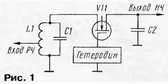
Encyclopedia of radio electronics and electrical engineering / Civil radio communications In the article brought to the attention of readers, options for mixer circuits made on field-effect transistors used in the controlled resistance mode (without a power source) are considered and discussed. Such mixers have a number of advantages that make it possible to significantly expand the dynamic range of receivers, especially heterodyne (direct conversion) receivers. In today's severe interference environment on the air, a large dynamic range of the mixer is important, which allows you to largely get rid of crosstalk, intermodulation and similar interference from powerful out-of-band signals, which are practically not attenuated by cascades installed before the main selection filter. If a number of measures can still be taken in the RF frequency converter to increase its linearity, then mixers are most often performed on non-linear elements (diodes, transistors), which, by the very principle of operation of many frequency-converting mixers, must be non-linear. For this reason, the dynamic range of the mixer is usually worse than the URCH. For a long time already, mixers based on field-effect transistors in the controlled active resistance mode have been proposed and used, the advantages of which have not yet been sufficiently evaluated. A diagram of the simplest mixer on a single field-effect transistor is shown in fig. 1.
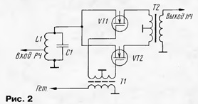
The signal from the input circuit is fed to the source of the transistor, and the IF or LF signal (in a heterodyne receiver) is taken from the drain. No power supply required. The local oscillator voltage is applied to the gate of the transistor and controls the channel resistance. It is known that at low voltages, the source-drain gap (channel) of a FET behaves like a linear resistor, regardless of the polarity of the applied voltage. At the same time, the channel resistance can vary depending on the gate-source voltage, from tens of ohms to many megohms. This allows the use of a field-effect transistor in mixers as a controlled linear element. The main advantages of the mixer include high sensitivity, since neither the supply current nor the local oscillator current passes through the transistor channel, but only a weak signal current, while the transistor makes a little more noise than a conventional resistor with the same resistance, and high linearity, since with a small input voltage, the conductance of the channel does not depend on it. In addition, the mixer features low LO signal penetration into the input circuit (only through a small capacitance between the gate and the transistor channel) and extremely low power required from the LO, since the input resistance in the gate circuit is high. Such a simple mixer provides a sensitivity of about 1 μV (without URF) and a dynamic range of about 65 dB. You can increase the dynamic range in the following classical ways: switch to a balanced circuit, ensure the operation of the mixer in the key mode and match the mixer with the load in a wide frequency band. Balanced FET mixer circuits were born from similar diode circuits, with the transistor channel connected instead of the diode, and the polarity of the latter corresponds to the in-phase or anti-phase connection of the gate to the local oscillator. On fig. 2 shows a diagram of a balanced mixer on two field-effect transistors. The signal is supplied to the sources of the transistors in phase, and the heterodyne voltage to the gates is antiphase, which ensures that the transistors open in turn by positive half-waves.
At the drains of transistors, the IF (LF) signals are out of phase, which requires the use of a low-frequency transformer T2 (in all diagrams, the magnetic circuits of the IF (LF) transformers are shown as a solid line, in contrast to the HF, where the magnetic circuits are shown as magnetodielectric). The mixer is balanced for both heterodyne and signal inputs. The first means that the heterodyne voltage does not reach the signal input, since two parasitic gate-channel capacitances are connected to the anti-phase terminals of the secondary winding of the transformer T1. The second means that parasitic conversion products, such as low-frequency currents, arising from direct detection of input signals, are applied to the anti-phase inputs of the low-frequency transformer and cancel each other out. Another variant of a simple balanced mixer circuit is shown in Fig. 3.
Here, the signal is fed to the channels of the transistors in antiphase, and the local oscillator voltage to the gates is in phase. As before, the mixer is balanced for heterodyne voltage. It is less obvious that the mixer is balanced in terms of direct detection of input signals. The fact is that the products of direct detection are in-phase at the drains of transistors (the device acts as a full-wave rectifier) and are compensated in the low-frequency transformer T2. The disadvantages of the described simple balanced mixers include the incomplete suppression of conversion by-products, in particular, the second harmonics of the input and heterodyne signals. The greatest purity of the spectrum is provided by two-balance mixers (analogues of ring mixers). The scheme of such a mixer on four transistors is given in fig. 4.
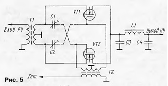
The mixer requires three balancing transformers installed on all inputs/outputs. Here, the channels of the transistors VT1, VT2 and VT3, VT4 are alternately carried out, connecting the terminals of the symmetrical windings of the transformers T1 and TK either directly (conduct VT1 and VT2), or crossed (conduct VT3 and VT4). This mixer gives excellent results in superheterodyne receivers, providing near the maximum dynamic range currently achievable. Of course, it is necessary to take all measures to improve the symmetry of transformers and select transistors with the same characteristics. When used in heterodyne receivers, mixers according to the schemes of fig. 2-4 have a major drawback associated with the presence of a low-frequency transformer, laborious to manufacture and subject to various pickups, including network ones with a frequency of 50 Hz. Distortions associated with the nonlinearity of the magnetic characteristics of the magnetic circuit are not excluded. The low-frequency transformer is absent in the mixer according to the scheme of fig. 5, where the input and heterodyne signals are supplied to two transistors in antiphase.
In fact, this is a transistor analogue of a two-diode balanced mixer. However, the mixer has disadvantages that are not immediately visible. It is not balanced on the heterodyne input. The antiphase signal of the local oscillator at the gates of the transistors seeps through parasitic capacitances to the extreme terminals of the symmetrical winding of the transformer T1 and is not compensated. In addition to the obvious harm caused by the radiation of the local oscillator signal through the antenna, namely the creation of interference with other nearby receivers, this is fraught with the reception of its own signal, but already modulated by the AC hum and other interference. There are at least two ways to solve the problem. The first is to add neutralizing capacitances - capacitors C1 and C2, connected crosswise with respect to the parasitic capacitances of transistors VT1 and VT2. By adjusting their capacitance, you can achieve significant suppression of the local oscillator signal at the input. This is also useful when using a mixer in transmission paths (after all, all the described passive mixers are completely reversible), when an audio signal is applied to the low-frequency input, and a balanced modulated DSB signal is removed from the high-frequency input. Another way is to use a transistor phase inverter instead of a balancing transformer T1, see fig. 6.
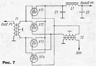
At the source and drain of the transistor VT1, equal and antiphase signal voltages are allocated, which are fed through the coupling capacitors C2 and C3 to the sources of the mixer transistors VT2 and VT3. In a heterodyne receiver, capacitors must have a significant capacitance, since not only high, but also audio frequency currents pass through them. In place of VT1, you can also use a bipolar transistor, but it has worse linearity and lower input resistance. The mixer is characterized by high suppression of the local oscillator signal at the input, which is facilitated by the anti-phase connection of the mixer transistors to the transformer T1, and the phase-inverted input stage. But this device also has a drawback: the output resistances along the source and drain circuits of the cascade on the VT1 transistor are different (the first one is below) and the phase inverter, generally speaking, is asymmetric. In the balance mixer shown in Fig. 7, the penetration of the local oscillator signal into the input circuit is reduced due to the fact that transistors VT1, VT3 with a p-channel are connected in parallel with the transistors VT2, VT4 with an n-channel, and the local oscillator voltage from the symmetrical winding of the transformer T2 is applied to transistors of opposite conductivity in antiphase. At the same time, transistors VT1 and VT2 open on one half-wave of the heterodyne voltage, and VT3 and VT4 open on the other. Parallel connection of the channels reduces the resistance of the mixer arms in the open state, in addition, improves the linearity of the mixer. By the way, this has long been used in bidirectional CMOS logic keys.
It is possible to use the mentioned switches in mixers, but, unfortunately, in CMOS logic elements, the antiphase control signal (heterodyne) for the p-channel transistor is formed from the signal coming to the gate of the p-channel transistor using an inverter. The latter has a rather long delay time (about 50 ns for the K561 MS series), as a result of which an additional phase shift appears, which worsens the operation of the mixer at high frequencies, in particular, the passage of the heterodyne signal to the mixer input is not completely eliminated. In conclusion, consider the operation of a very interesting and simple mixer, proposed specifically for heterodyne receivers (Fig. 8). It is made on two identical field-effect transistors, the channels of which are connected in parallel, and anti-phase heterodyne voltages from the symmetrical winding of the transformer T1 are applied to the gates. Transistors should be closed at zero gate voltage and open only at peaks of the heterodyne voltage. As a result, the mixer opens twice during the period of the heterodyne voltage, and the local oscillator frequency is chosen to be half the signal frequency.
This is very beneficial, in particular, for VHF receivers (fewer frequency multiplication steps are required) and in general for all heterodyne receivers, since the local oscillator signal "leaked" into the antenna circuit is effectively suppressed by the input filter. The use of this mixer is promising in synchronous heterodyne VHF receivers, where low penetration of the local oscillator signal into the input circuits is extremely important. However, this mixer is only balanced on the LO input, not on the signal input. Therefore, parasitic direct detection of powerful interfering signals on the transition nonlinearity, source-drain transistors is possible. Author: M. Syrkin (UA3ATB)
The world's tallest astronomical observatory opened
04.05.2024 Controlling objects using air currents
04.05.2024 Purebred dogs get sick no more often than purebred dogs
03.05.2024
▪ Traces of Icelandic eruptions ▪ Adhesive frameless solar panels
▪ section of the website Residual current devices. Selection of articles ▪ article Developmental psychology. Lecture notes ▪ article Why did a small island 42 km long become famous as a ship-eater? Detailed answer ▪ article Functional composition of Loewe TVs. Directory ▪ article Theft indicator. Encyclopedia of radio electronics and electrical engineering
Home page | Library | Articles | Website map | Site Reviews www.diagram.com.ua |


 Arabic
 Bengali
 Chinese
 English
 French
 German
 Hebrew
 Hindi
Hindi Italian
 Japanese
 Korean
 Malay
Malay Polish
 Portuguese
 Spanish
 Turkish
 Ukrainian
 Vietnamese


 Leave your comment on this article: