
|
|
ENCYCLOPEDIA OF RADIO ELECTRONICS AND ELECTRICAL ENGINEERING Miniature radiotelephone. Encyclopedia of radio electronics and electrical engineering
Encyclopedia of radio electronics and electrical engineering / Telephony The increased interest in the manufacture of radiotelephones is constrained by the complexity of circuit and technical solutions, due to the principle of operation. For example, the radiotelephone "RTF-92", published in [1], is difficult both to manufacture and to set up, requires the manufacture of a large number of coils and transformers When developing the proposed radiotelephone, the task was to create a radiotelephone available for manufacturing by novice radio amateurs. The radio tone control method does not allow this, therefore the operation of this radiotelephone is based on the carrier interruption method. This made it possible to simplify the circuit as much as possible and provide the following advantages:
Consider the operation of the radiotelephone.
The cordless handset (Fig. 1) is in the door reception mode, its transmitter is turned off. In a stationary telephone (Fig. 2), only one receiver also works. Caller ID phone is in auto-hook mode. When a call is received from the subscriber, the transmitter of the stationary device is automatically turned on and transfers the call to the cordless handset. When a call is received, the handset transmitter is turned on and the system is ready for duplex operation.
When calling from the side of the handset, the transmitter is powered by the toggle switch S1 "Standby". The carrier signal is received by the receiver of the stationary device, and the fine tuning LED lights up in it. In standby mode, the transistor VT1 (Fig. 2) is closed. With the voltage from the LED, the transistor opens, while a voltage drop occurs on the resistor R5, which feeds the transmitter of the stationary part. When dialing a number on the handset, the power supply (and, accordingly, the carrier) is interrupted for the number of times corresponding to the digit. Accordingly, the LED goes out the same number of times, the voltage from which the transistor VT1 switches. This is how the line is dialed. When transmitting information, a low-frequency signal from the output of the ULF receiver is fed to the VT1 base for modulation. If you do not have a telephone with caller ID, which includes the auto-pick up mode, you can install an electronic relay that performs auto-pickup. Selection of receivers and transmitters for the radiotelephone. The choice of receiver depends on the capabilities and qualifications of the radio amateur. The main criterion for the receiver is that the controls and transistor VT1 can be placed in the receiver itself. You can also install a socket in the receiver housing, and output control voltages to it, and assemble the control circuit itself in a separate housing. In this embodiment, the receiver can be disconnected at any time and used for its intended purpose. If an imported receiver is used (they usually use one specialized microcircuit), and also in the absence of a receiver circuit diagram, the point from which the fine-tuning voltage is removed can be found experimentally by a tester by increasing the constant voltage when receiving a carrier frequency signal from the radiotelephone transmitter transmitter.
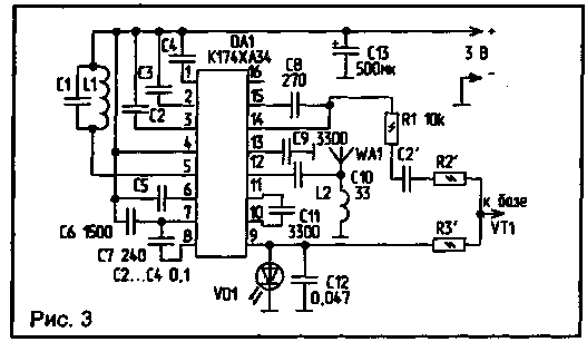
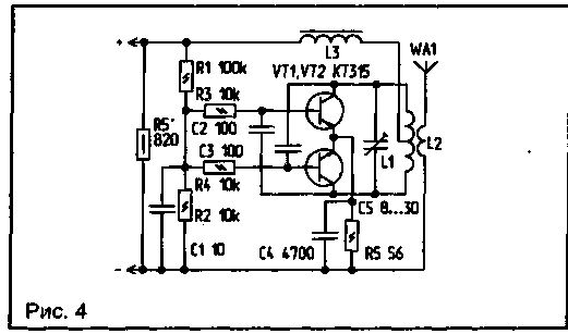
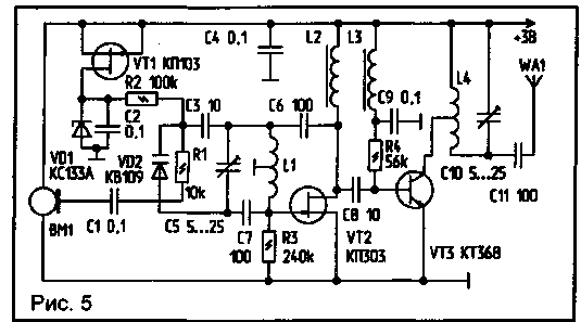
To simplify the design, the transmitter of a stationary device (Fig. 4) is powered by a telephone line. Its power is limited by the power of the telephone network and depends on the voltage drop across the resistor R5. The value of R5 is selected in such a way that when the handset is raised, 15 ... 18 V drops on it (the transistors should warm up slightly). The range of the radiotelephone receiver receiver is the quiescent current, since the time of continuous operation depends on it. An economical low-voltage receiver can be assembled on a K174XA34 chip according to the circuit shown in Fig. 3. If it is not available, you can use a ready-made miniature receiver with an output to the phone. The dimensions of the board are such that they allow you to freely install it in the handset of the radiotelephone. The same receiver, but for the range of 65 ... 74 MHz, can also be used for a stationary device. The receiver draws little current, so it can be powered from the telephone line. But since the dimensions of the receiver for a stationary device are not critical, a portable receiver with a built-in power supply unit of the "Ocean" type can be used for this purpose. The procedure for finalizing the receiver of a stationary device. To control the transistor VT1 (Fig. 2) from the receiver, two signals are used: fine-tuning voltage - for dialing a number into the line, and low-frequency voltage - for modulation. If the size of the radiotelephone is largely determined by the power of the transmitter of the handset, and that, in turn, depends on the supply voltage. If long range is not required, the transmitter can be powered by the receiver (Figure 1). The choice of voltage source and its value is determined by the size of the radiotelephone handset Schematic diagram of the radiotelephone handset transmitter is shown in Fig.5. The transmitter master oscillator is made on a VT2 transistor of the KP303 type. The generation frequency is determined by the elements L1, C3, C5, VD2. Frequency modulation is carried out by applying a modulating audio frequency voltage to the VD2 varicap type KV109. The operating point is set by the voltage supplied through the resistor R2 from the voltage regulator. The stabilizer includes a stable current generator on a field-effect transistor VT1, a zener diode VD1 and a capacitor C2. The power amplifier is made on the transistor VT3. The operating mode of the amplifier is set by resistor R4.
Inductors L2 and L3 can be any with an inductance of 10 ... 150 mH. Coils L1 and L4 are wound on polystyrene frames with a diameter of 5 mm with tuned cores of 100 HF or 50 HF. The number of turns is 3,5 with a tap from the middle, the winding pitch is 1 mm, the wire is PEV 0,5. The setting consists in setting the required frequency of the generator with capacitor C5, obtaining maximum power by selecting the resistance of resistor R4 and adjusting the frequency of the circuit with capacitor C10. In the transmitter of a stationary device (Fig. 4), the resistor R5 is included in the break of one of the wires of the telephone network. When you pick up the handset of the telephone or turn on the auto-lift mode, a current appears in the circuit, which, depending on the type of device and the state of the line, is in the range of 10 ... 35 mA. This current, flowing through the resistor R5, causes a voltage drop of the order of 15 ... 18 V on it, which feeds the transmitter. The transmitter oscillator is assembled according to the usual push-pull circuit, on transistors VT1 and VT2. Frequency modulation occurs due to a change in the voltage in the line and, as a result, a change in the voltage at the bases of the transistors. The frequency is set by the loop parameters L1, C5. Coil L1 is wound on a polystyrene frame with a diameter of 5 mm and contains 4 turns of PEV wire 0,5 mm with a tap from the middle. Coil L2 is wound on top of L1 and has 2 turns of the same wire. The setting is made when the telephone line is busy by adjusting the circuit L1, C5. The radiotelephone provides a communication range within 300 meters, but when installing additional power amplifiers in the radiotelephone handset and the stationary part, you can easily increase the range up to 10...15 km. When installing a radiotelephone in a car, it is better to power the radiotelephone handset from the on-board battery. Consultations, as well as assembled transmitter circuits, can be obtained from the author. Literature
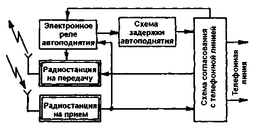
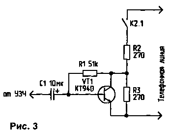
Author: N. Martynyuk, Brest region, Kobrin Many letters have been received regarding my article, and therefore I am trying to answer the basic questions on the pages of the magazine. The auto-lift relay (Fig. 1) is made on the K176LA7 microcircuit according to the single vibrator circuit. Since the receiver and transmitter of the fixed part are powered by a telephone line, an increase in the range of action is possible only by increasing the sensitivity of the receivers, because. The power of a fixed transmitter is limited by the power of the telephone line, while that of a portable transmitter is limited by the battery capacity. Making powerful transmitters and highly sensitive receivers at home requires some experience, tuning devices and scarce radio components, so it’s better to go the other way if you need a radiotelephone with a range of up to 20 ... 30 km. Currently, a good 40-channel radio station can be purchased relatively inexpensively. Through simple modifications, its power can be increased to 8 ... 10 W, and on the basis of such radio stations a good radiotelephone with a large range is obtained. Its functional diagram is shown in Fig. 2, and the circuit diagrams of the electronic relay, auto-raising and matching delay units are shown in Fig. 3, 4.
In standby mode, only the receiving radio is turned on. When a call signal is received from the telephone line, the ringing voltage is applied to the electronic auto-lift relay, which is activated and the executive relay turns on the radio station, which is transmitting. Call signals are fed to its microphone input and transmitted over the air to a mobile radio station. After 5...6 s, the auto-pickup delay circuit is triggered, and a connection is made with the caller. Since reception is on one channel and transmission on another, the mobile radio must change channel when transmitting. For example, reception is carried out on the 9th channel, and before you press the PTT to transmit, you should turn on the 19th channel. Author: N. Martynyuk, Brest region, Kobrin; Publication: N. Bolshakov, rf.atnn.ru
Artificial leather for touch emulation
15.04.2024 Petgugu Global cat litter
15.04.2024 The attractiveness of caring men
14.04.2024
▪ E-bike with face recognition ▪ Full featured Thecus NAS 2U server ▪ Cellulose Water Purification ▪ Bilingualism improves perception of information and attentiveness
▪ section of the site Power supply. Article selection ▪ article Trouble, since the cobbler starts the oven pies ... Popular expression ▪ article Where do ants live that can count the number of steps taken? Detailed answer ▪ article The functional composition of Thomson TVs. Directory
Comments on the article: Mihailo Haven't figured it out yet, but I like it.
Home page | Library | Articles | Website map | Site Reviews www.diagram.com.ua |


 Arabic
 Bengali
 Chinese
 English
 French
 German
 Hebrew
 Hindi
Hindi Italian
 Japanese
 Korean
 Malay
Malay Polish
 Portuguese
 Spanish
 Turkish
 Ukrainian
 Vietnamese



 Leave your comment on this article: