8W LED lamp power supply on HV9961. Encyclopedia of radio electronics and electrical engineering

Encyclopedia of radio electronics and electrical engineering / Power Supplies
 Comments on the article
The authors offer an 8 W power supply, assembled on the HV9961 chip, to power an LED lamp.
Nowadays, in the literature and the Internet, there are many descriptions of power supplies of various complexity and functionality for LED light sources, often called LED drivers. These are power supplies, usually pulsed, with output current or voltage stabilization. The power supply proposed in this article is a variant of one of the inexpensive light sources mass-produced by a domestic manufacturer. It is simple, which makes it accessible for repetition even by novice radio amateurs and at the same time has good parameters.
Main Specifications
- Input AC voltage, V.......120...250
- Output current, mA.......65
- Stability of output current in the entire range of supply voltage, no more than, % ......2
- Maximum output voltage, V ....... 110
- Coefficient of pulsation of the luminous flux, no more than, % ..... 1,5
The power supply is a buck-converter controlled by a widely used specialized HV9961 current regulator microcircuit. The scheme of the device is shown in fig. 1. A small number of external elements and a fairly high accuracy of load current regulation have made this microcircuit a common solution for various LED drivers.

Rice. 1. Diagram of the device (click to enlarge)
The load current is controlled by changing the average current value of the switching transistor VT1. By measuring the voltage drop across the resistor R2, the DA1 microcircuit corrects the time (duration) of the open state of the transistor VT1 and thus maintains the output current at a given level. In this case, the time of the closed state, set by the resistor R1, is always constant.
Resistor R2, in fact, is a current sensor through the LEDs. Its resistance is calculated by the formula
R2 = 0,275 / ILED
where ILED - required LED current.
Off time toff (µs) transistor states are calculated by the formula
toff = R1/25 + 0,3
where the resistance of the resistor R1 is in kiloohms.
It is desirable to choose the resistance of the resistor in the range from 100 kΩ to 1 MΩ, although in [1] a wider range is allowed - from 30 kΩ. Too little time of the closed state can lead to overheating of the transistor VT1.
The inductance of the inductor L2 can be estimated quite accurately from the relation

where the inductance is obtained in henry, if the voltage is substituted into the formula in volts, the current is in amperes, and the time is in seconds.
When calculating the power supply for other output current and power, the inductance of the inductor may have to be manually adjusted by selection, achieving stable operation of the device at different input voltages. And we must not forget that a non-magnetic gap is required for the L2 choke. You can calculate the gap, for example, according to the method [2] or [3].
For this design, the inductor L2 was wound on a standard frame for the E 16/8/5 magnetic core from Epcos made of N87 material, the non-magnetic gap was 0,5 mm (the total gap of the magnetic core). The winding contains 700 turns of wire with a diameter of 0,15 mm.

Rice. 2. PCB drawing of the device
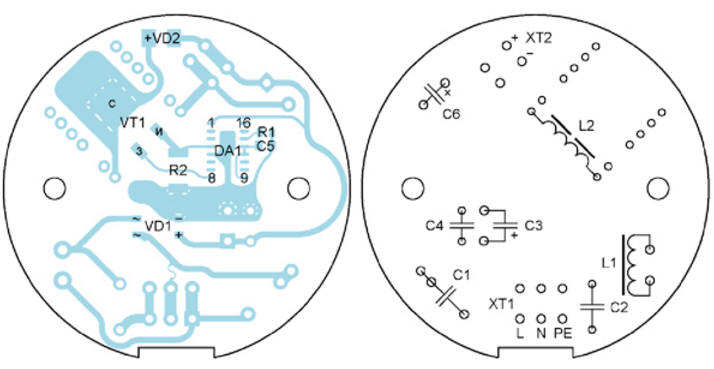
Rice. 3. Location of power supply parts
The power supply is assembled on a printed circuit board made of fiberglass laminated on one side with a thickness of 1,5 mm. Its drawing is shown in Fig. 2, and the location of the parts - in Fig. 3. On the side of the printed conductors, there is a DA1 chip, a VT1 transistor, a VD1 diode bridge, a VD2 diode, a capacitor C5 and resistors R1, R2. The device uses imported capacitors, C1 and C4 - for an alternating voltage of 250 V. It is permissible to replace them with capacitors K73-17 for a rated voltage of 630 V (C1) and 400 V (C4). The rated voltage of the capacitor C2 must be at least 1,5 kV. This condition is satisfied, for example, capacitors K15-5. Diode VD2 - HS1M or a similar high-speed diode in an SMA package (DO-241AC) with a reverse voltage of at least 400 V and a current of 1 A.
The STD5N52K3 transistor in the D-PAK package can be replaced by any n-channel MOSFET with a drain-source voltage of 500 V, a channel resistance of 1 ... screw terminal blocks, respectively, three- and two-pin for mounting on the board. A photograph of the mounted printed circuit board from the side of the printed conductors is shown in fig. 2.
The LED board is made on an aluminum base for better heat dissipation. It has 36 serially connected and evenly spaced Nichia NESL157BT sw30 LEDs (Fig. 5).

Rice. 4. Mounted printed circuit board

Rice. 5. Mounted device
Literature
- LED Driver with Average-Mode Constant Current Control. - URL: pdf1.alldatasheet.com/datasheet-pdf/view/637222/SUTEX/HV9961.html.
- Kuznetsov A. Transformers and chokes for SMPS. Rev 2. - URL: servotechnica.spb.ru/library/BOOKS/$D2$F0$E0$ED$F1$F4$EE$F0$EC$E0$F2$EE$F0$FB.
- Brown M. Power sources. Calculation and design. Per. cand. tech. Sciences S. L. Popov. - Kyiv, MK-Press, 2007.
Authors: V. Lazarev, D. Golubin
 See other articles Section Power Supplies.
Read and write useful comments on this article.
<< Back
 Latest news of science and technology, new electronics:
Machine for thinning flowers in gardens
02.05.2024
In modern agriculture, technological progress is developing aimed at increasing the efficiency of plant care processes. The innovative Florix flower thinning machine was presented in Italy, designed to optimize the harvesting stage. This tool is equipped with mobile arms, allowing it to be easily adapted to the needs of the garden. The operator can adjust the speed of the thin wires by controlling them from the tractor cab using a joystick. This approach significantly increases the efficiency of the flower thinning process, providing the possibility of individual adjustment to the specific conditions of the garden, as well as the variety and type of fruit grown in it. After testing the Florix machine for two years on various types of fruit, the results were very encouraging. Farmers such as Filiberto Montanari, who has used a Florix machine for several years, have reported a significant reduction in the time and labor required to thin flowers.
... >>
Advanced Infrared Microscope
02.05.2024
Microscopes play an important role in scientific research, allowing scientists to delve into structures and processes invisible to the eye. However, various microscopy methods have their limitations, and among them was the limitation of resolution when using the infrared range. But the latest achievements of Japanese researchers from the University of Tokyo open up new prospects for studying the microworld. Scientists from the University of Tokyo have unveiled a new microscope that will revolutionize the capabilities of infrared microscopy. This advanced instrument allows you to see the internal structures of living bacteria with amazing clarity on the nanometer scale. Typically, mid-infrared microscopes are limited by low resolution, but the latest development from Japanese researchers overcomes these limitations. According to scientists, the developed microscope allows creating images with a resolution of up to 120 nanometers, which is 30 times higher than the resolution of traditional microscopes. ... >>
Air trap for insects
01.05.2024
Agriculture is one of the key sectors of the economy, and pest control is an integral part of this process. A team of scientists from the Indian Council of Agricultural Research-Central Potato Research Institute (ICAR-CPRI), Shimla, has come up with an innovative solution to this problem - a wind-powered insect air trap. This device addresses the shortcomings of traditional pest control methods by providing real-time insect population data. The trap is powered entirely by wind energy, making it an environmentally friendly solution that requires no power. Its unique design allows monitoring of both harmful and beneficial insects, providing a complete overview of the population in any agricultural area. “By assessing target pests at the right time, we can take necessary measures to control both pests and diseases,” says Kapil ... >>
| Random news from the Archive MG Dynamo electric car
27.04.2014
British automaker MG, celebrating its 90th anniversary this year, has unveiled the concept of a compact all-electric Dynamo hatchback.
The small car has a three-door design. It is designed primarily for city driving. The length is 3569 mm, own weight - 1080 kg.
With a fully charged battery pack, the car is said to be able to travel up to 80 km, although in practice this figure is likely to be less. Charging the batteries to 80% capacity will take approximately half an hour, and 100% replenishment of the energy reserve will take at least two hours.
The electric propulsion system delivers a maximum output of 70 horsepower and delivers 155 Nm of torque. The acceleration time from 0 to 100 km / h is not specified, but the manufacturer notes that the electric car passes the mark of 50 km / h in 5,3 seconds from the start.
Dynamo is MG's first all-electric vehicle. When the new product reaches the market, it is not specified.
The launch of Dynamo in the UK could come in handy as the country plans to roll out a massive network of electric car charging stations. It is assumed that by 2020 up to 70 thousand specialized points will appear in the territory of Foggy Albion to recharge the batteries of hybrid cars and all-electric vehicles. And in London, a short-term electric car rental service should be launched in the near future. According to the plan, the fleet of such electric cars will have 100 vehicles by the end of this year. In the future, their number is planned to be increased to 3000. The cost of rental will be about 12 euros per hour.
|
Other interesting news:
▪ Scientists have determined the importance of relativistic effects for objects
▪ Optical fiber from food agar
▪ Steadicam for smartphones Xiaomi Mijia
▪ Microwave oven that chooses how to cook food
▪ South Korea launches 5G network
News feed of science and technology, new electronics
 Interesting materials of the Free Technical Library:
▪ website section LEDs. Article selection
▪ article Chewing gum for the eyes. Popular expression
▪ article What is aphid? Detailed answer
▪ article Peg (leg of lamb). Travel Tips
▪ article Inductive sensors. Encyclopedia of radio electronics and electrical engineering
▪ article Scheme, pinout (pinout) of Siemens C60 cable with GPRS support. Encyclopedia of radio electronics and electrical engineering
Leave your comment on this article:
 All languages of this page
Home page | Library | Articles | Website map | Site Reviews

www.diagram.com.ua
2000-2024


 Arabic
 Bengali
 Chinese
 English
 French
 German
 Hebrew
 Hindi
Hindi Italian
 Japanese
 Korean
 Malay
Malay Polish
 Portuguese
 Spanish
 Turkish
 Ukrainian
 Vietnamese