Indicator of the charging process in the memory on the basis of a computer PSU. Encyclopedia of radio electronics and electrical engineering

Encyclopedia of radio electronics and electrical engineering / Chargers, batteries, galvanic cells
 Comments on the article
The indicator allows you to track all stages of charging a car battery. Information is displayed by four LEDs of different colors.
In the articles of V. Andryushkevich [1] and [2], the method of converting computer power supplies (PSU) into a charger (RAM) was quite simply and clearly stated. But the charging process indicator, in my opinion, has some drawbacks. In the proposed indicator, the scheme of which is based on the combination of the corresponding nodes from [1] and [2] and is shown in fig. 1 have been eliminated. The node for indicating the achievement of the maximum charging voltage is made on the op-amp DA1.2. Due to the large gain, it works almost like a comparator.
The threshold turn-on voltage is 14,7 V, it is set with a trimming resistor R4. The reference voltage of +5 V is taken directly from pin 14 (UREF) of the TL494CN PSU chip. When the maximum voltage is reached at the output terminals of the charger, the HL1 LED (green) turns on and shines until the charger is turned off, indicating that the charging voltage has reached its maximum value, and the process of reducing the charging current is underway.

Rice. 1. Scheme of the proposed indicator
Scheme of nodes on the OS DA1. 1 and comparator DA2 is similar to that shown in fig. 2 in [2]. There is also a method for setting them up. The values of the resistors R38, R39 [2] are reduced to reduce interference from the PSU voltage converters, and the indicator is powered directly from the output of the memory. This ensures automatic extinguishing of all LEDs HL1-HL4 in the presence of a short circuit at the output.

Rice. 2. Printed circuit board and elements on it
At the beginning of the charging process at the rated current, which I have set to 6 A, the red HL2 LED lights up. When the maximum charging voltage is reached, the HL1 LED lights up. When the charging current drops to 3 ... 4 A (set by a trimming resistor R3), the HL2 LED goes out and HL3 turns yellow. When the charging current becomes less than 0,5 ... 1 A (set by a trimming resistor R10), HL3 will go out and the blinking green LED HL4 will turn on, indicating the completion of charging. Such an indication algorithm gives visual control of all its stages.
The memory itself was assembled on the basis of an outdated, but once quite common computer PSU model PM-230W [3] from KME. The design of the indicator printed circuit board is adapted for this and similar PSUs. However, nothing prevents you from installing it on other PSUs. Just connecting the indicator to the PSU will have to be done with five additional pieces of flexible wires in isolation. On the printed circuit board of the indicator, these connections are routed for soldering onto a standard nine-pin angle connector installed on the main PSU board of the specified model. Prior to revision, the module of the start-up block by the "Power On" signal was attached to it [3].
All elements, except for the HL1-HL4 LEDs, are placed on a printed circuit board, the drawing of which and the location of the elements on it are shown in fig. 2. The LEDs are fixed in the holes on the front wall of the memory case. When reworking the PSU, of course, all its extra elements are dismantled. Chips LM358N and LM393N are often used in the launch node. After dismantling, they can be used in the indicator.
Fixed resistors C2-23, MLT, tuning resistors from the SH-625MC, PV-32, CA9H2.5, 3362S series are used. If the PSU of the PM-230 series is to be reworked, the launcher board is unsoldered from the nine-pin pin connector, and the indicator board is installed in its place in the released pins and the contact pads are soldered. The contact pads for terminals 7 and 8, 9 on the PSU board are connected with short wires, respectively, to the current sensor (R24 in Fig. 1 in [1]) and the +13,9 V line. If the soft (slow) start circuit is installed on the main board, as, for example, R5C11 in [1], the indicator elements R12 and C4 are not set. The charger with the cover removed and the built-in indicator is shown in fig. 3.
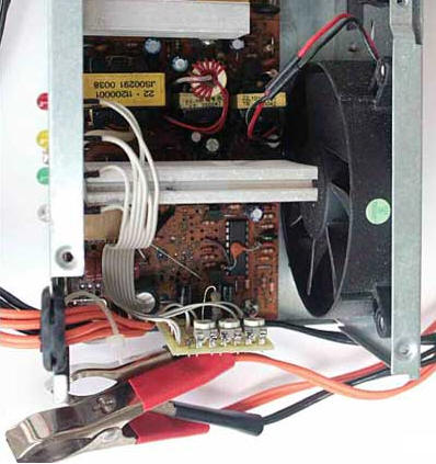
Rice. 3. Charger with cover removed and built-in indicator
PCB drawings in Sprint LayOut 5.0 format and charger diagram based on PSU PM-230W in GIF format can be downloaded from ftp://ftp.radio.ru/pub/2016/11/zar.zip.
Literature
- Andryushkevich V. Alteration of a computer power supply into a laboratory and charger. - Radio, 2012, No. 3, p. 22-24.
- Andryushkevich V. Alteration of a computer power supply into a charger. - Radio, 2013, No. 9, p. 26, 27.
- PM-230W. - URL: electro-tech.narod.ru/schematics/power/comp/atx/kme_pm-230.gif.
Author: S. Glibin
 See other articles Section Chargers, batteries, galvanic cells.
Read and write useful comments on this article.
<< Back
 Latest news of science and technology, new electronics:
Machine for thinning flowers in gardens
02.05.2024
In modern agriculture, technological progress is developing aimed at increasing the efficiency of plant care processes. The innovative Florix flower thinning machine was presented in Italy, designed to optimize the harvesting stage. This tool is equipped with mobile arms, allowing it to be easily adapted to the needs of the garden. The operator can adjust the speed of the thin wires by controlling them from the tractor cab using a joystick. This approach significantly increases the efficiency of the flower thinning process, providing the possibility of individual adjustment to the specific conditions of the garden, as well as the variety and type of fruit grown in it. After testing the Florix machine for two years on various types of fruit, the results were very encouraging. Farmers such as Filiberto Montanari, who has used a Florix machine for several years, have reported a significant reduction in the time and labor required to thin flowers.
... >>
Advanced Infrared Microscope
02.05.2024
Microscopes play an important role in scientific research, allowing scientists to delve into structures and processes invisible to the eye. However, various microscopy methods have their limitations, and among them was the limitation of resolution when using the infrared range. But the latest achievements of Japanese researchers from the University of Tokyo open up new prospects for studying the microworld. Scientists from the University of Tokyo have unveiled a new microscope that will revolutionize the capabilities of infrared microscopy. This advanced instrument allows you to see the internal structures of living bacteria with amazing clarity on the nanometer scale. Typically, mid-infrared microscopes are limited by low resolution, but the latest development from Japanese researchers overcomes these limitations. According to scientists, the developed microscope allows creating images with a resolution of up to 120 nanometers, which is 30 times higher than the resolution of traditional microscopes. ... >>
Air trap for insects
01.05.2024
Agriculture is one of the key sectors of the economy, and pest control is an integral part of this process. A team of scientists from the Indian Council of Agricultural Research-Central Potato Research Institute (ICAR-CPRI), Shimla, has come up with an innovative solution to this problem - a wind-powered insect air trap. This device addresses the shortcomings of traditional pest control methods by providing real-time insect population data. The trap is powered entirely by wind energy, making it an environmentally friendly solution that requires no power. Its unique design allows monitoring of both harmful and beneficial insects, providing a complete overview of the population in any agricultural area. “By assessing target pests at the right time, we can take necessary measures to control both pests and diseases,” says Kapil ... >>
| Random news from the Archive Nanoparticles will stop old age
19.10.2012
A team of Spanish scientists have developed "smart" nanoparticles that could potentially be used to combat the symptoms of aging.
Specially designed nanoparticles can selectively release drugs in old human cells. The potential of this technology is very large: it can cope with such ailments as cancer, cell degeneration, Alzheimer's, Parkinson's, etc.
"Smart" mesoporous silicon nanoparticles contain galactooligosaccharides that prevent drug release in young healthy cells and release it in aging cells. In other words, for the first time, scientists have been able to create a "guidance system" that directs the drug precisely to the degenerative cells that cause various diseases.
During the experiments, the researchers have already evaluated the effectiveness of new nanoparticles. In particular, it was possible to influence old cells that secrete beta-galactosidase, an enzyme that is characteristic of aging cells. Scientists have developed special nanoparticles that "target" this enzyme, thus detecting old cells and destroying them, opening the way for self-rejuvenation of the body.
Cellular aging is a physiological process that eliminates too old and damaged cells that do more harm than good to the body. When a person is young, the mechanisms of aging prevent many diseases, such as the development of tumors. The problem is that with age, there are more and more aging cells - they accumulate in organs and tissues, disrupting the normal functioning of the body. The discovery of Spanish scientists shows that medicine can use a targeted effect on old cells: treat them or destroy them.
|
Other interesting news:
▪ Animals see human anger
▪ Microsoft will decipher the human immune system
▪ A painted window becomes a solar panel
▪ Electric backpacks for soldiers
▪ Solar panels are thinner than cobwebs
News feed of science and technology, new electronics
 Interesting materials of the Free Technical Library:
▪ site section Digital technology. Article selection
▪ Podshof article. Popular expression
▪ article How many kilometers between the Pacific and Atlantic oceans? Detailed answer
▪ Areca palm article. Legends, cultivation, methods of application
▪ article How to test the unknown iron of a welding transformer. Encyclopedia of radio electronics and electrical engineering
▪ article Putting on the ring with hands tied. Focus Secret
Leave your comment on this article:
 All languages of this page
Home page | Library | Articles | Website map | Site Reviews

www.diagram.com.ua
2000-2024


 Arabic
 Bengali
 Chinese
 English
 French
 German
 Hebrew
 Hindi
Hindi Italian
 Japanese
 Korean
 Malay
Malay Polish
 Portuguese
 Spanish
 Turkish
 Ukrainian
 Vietnamese