|
|


 Arabic
 Bengali
 Chinese
 English
 French
 German
 Hebrew
 Hindi
Hindi Italian
 Japanese
 Korean
 Malay
Malay Polish
 Portuguese
 Spanish
 Turkish
 Ukrainian
 Vietnamese
|
ENCYCLOPEDIA OF RADIO ELECTRONICS AND ELECTRICAL ENGINEERING Safe charger
Encyclopedia of radio electronics and electrical engineering / Chargers, batteries, galvanic cells In the proposed design, the emphasis is on the safety of charging. The device checks the correct connection of the battery, automatically turns it off when charging is completed, stops charging when the battery is heated above the set temperature. It is known that even the fast charging algorithm (current 1...2C, where C is the battery capacity) assumes the duration of the charging process 1...5 hours [1]. It is hard to imagine that all this time the process will be monitored. And despite the fact that fast charging is the most dangerous. Even with a slight non-compliance with the regime, a rupture of the battery case is possible with all the ensuing consequences. Standard charging with a current of 0,1C is much safer, but it lasts too long (up to 14 ... 16 hours). The described device provides accelerated charging (4...7 h) of one Ni-Cd or Ni-MH battery with a capacity of 250 to 1000 mAh. A wide range of charging current is by no means conducive to the safety of the device due to possible user errors when setting the charging current, so there are various ways to protect the battery and the charger itself. The result is a device that may seem unnecessarily complex. However, this complexity will pay off with extended battery life and peace of mind for the fire situation in the apartment. The ability to charge only one battery is due to the desire to ensure a complete and, again, safe charge. From the technical characteristics of the device, it should be noted the "soft" mode of accelerated charging, automatic shutdown of the battery after charging is completed, protection against reverse polarity of its connection and overheating, mode indication, sound notification of emergency mode and, finally, a rather low supply voltage (from 3,5, XNUMXB), which in some cases may be highly desirable. The schematic diagram of the device is shown in fig. 1.
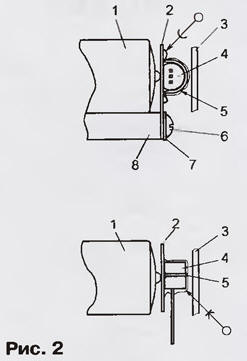
Its main part - the current stabilizer - consists of three nodes: a master voltage regulator and two identical current regulators. The main regulator (DA6.1, VT3) provides a charging current of 0,1C and works throughout the entire cycle. The second regulator (DA6.2, VT4) - it can be called forced - gives out a current equal to 0.ZC, and turns on when the voltage on the battery is more than 0,6 V, but has not reached 1,4 V. At this time, both regulators work and, being connected in parallel, feed the battery with a total current of 0,4C. Restrictions on the operation of the forced current regulator are due to the following. If the battery is heavily discharged (the voltage on it is Uac < 0,6 V), it is not safe to charge it with a large current, therefore charging is carried out with a current of 0,1C with the participation of only the main current regulator. When the voltage Uakk reaches 1,4 V, the forced regulator turns off, since this voltage is close to the limit, and it is advisable to carry out further charging with a standard current of 0,1C. Upon reaching Uacc = 1,48 V, it turns off and the main regulator - charging stops. In this case, the HL3 LED ("Charging") goes out, and HL1 ("Charging completed") lights up. Diodes VD1, VD2 prevent the battery from discharging after charging stops. Both regulators are voltage controlled current sources. The control voltage (relative to the positive power wire) is formed by the master voltage regulator DA3 and is regulated by a variable resistor R23 (they set the required charging current depending on the battery capacity). A feature of the KR1446UD1A op-amps used in current regulators [2] is the ability to operate at low supply voltages (from 2,5 V for unipolar), and most importantly, that the range of their input and output signals is almost equal to the sum of the supply voltages. In our case, DA6.1 operates with an input voltage equal to Us - UR25, where Us is the positive supply voltage, and UR25 is the voltage drop across the measuring resistor R25. The latter, in fact, is a "copy" of the control voltage (as is known, the voltages at both inputs of the OA covered by the OOS coincide up to zero bias voltage). Thus, with a charging current of 25 mA (for a battery with a capacity of 250 mAh), UR25 = 0,2 V. This means that the input voltage can be only 0,2 V less than the positive supply voltage of the op-amp DA6.1. Common op-amps allow operation with input voltages of not more than (Us - 1,5 ... 2) V. The same can be said about output voltages. During the charging process, DA6.1 provides an output voltage equal to Us - UR25 - UBE VT3, where UBE VT3 is the forward voltage at the emitter junction VT3 (0,6 ... 0,8 V). To stop the current regulator, the op-amp provides a voltage equal to Us, thus closing the transistor. All of the above applies to the forced regulator on DA6.2. Both regulators are turned off by transistors VT1 and VT2, respectively (more precisely, VT1 does this, since when it opens, it shunts resistors R21, R23, from which voltage is applied to the inputs of both op-amps). In the off state, the output current of the regulator is not equal to zero, since the voltage across the resistor R25 is not equal to zero. There are two reasons for this. Firstly, the resistance of the channel of the open field-effect transistor VT1 is non-zero, and therefore the voltage USI VT1 is a few millivolts. The second reason is the zero bias voltage of the op-amp DA6.1. As a result, the voltage across the resistor R25 depends on the sign of the zero bias voltage and is equal to USI VT1 ± UCM DA6.1. In this case, it is better to use the op-amp KR1446UD1A, its bias voltage does not exceed ±3 mV, therefore, in the off state, the regulator produces a small residual current of 1 ... 3 mA. The forced current regulator behaves in the same way. As a result, after charging is completed, the current stabilizer maintains a certain voltage on the battery, which prevents its discharge due to self-discharge and leakage current through the device circuits. Such a small current cannot harm the battery. In addition, this feature provides the device with stability when the battery is removed and the input voltage is applied. The current set by the main regulator is equal to Ureg / R25, where Ureg is the voltage drop across the resistors R21 + R23 (excluding the zero bias voltage of the op-amp DA6.1, its input current and the leakage current of the closed channel VT1). Ureg depends on the stabilization voltage DA3 ( 2,5 V) and the division ratio of the voltage divider R21-R23 (as noted, it is counted from the "plus" of the power supply). The current set by the forced regulator is determined similarly. Let us now turn to the second part of the device, consisting of a model voltage driver, comparators, which are used as the op amps of the DA4, DA5 microcircuits, and a logical node. As can be seen from the diagram, the voltage from the battery is not supplied directly to the inputs of the comparators DA4.1-DA4.4, but through resistors R14, R16-R18, in order to avoid damage to the op-amp when the battery is inserted and the charger is turned off. Resistors on the "reference" inputs eliminate the error caused by the op-amp's input currents (but not the difference in input currents). The "exemplary" input of the op-amp DA4.3 does not have such a resistor, since high accuracy is not required from this comparator. Comparator DA4.1 determines the moment when the forced current regulator is turned off (when the battery voltage reaches 1,4 V), DA4.2 - the moment when charging is completed and gives a signal to turn off the main current regulator. Resistor R24, which creates a positive feedback, forms a small (about 40 mV) hysteresis, which makes it possible to avoid an unstable state of the comparator after charging stops. Comparator DA4.3 gives a signal to turn on the forced current regulator when the voltage on the battery exceeds 0,6 V, and DA4.4 "checks" the correct connection of the battery: if the polarity is wrong, the current regulators are turned off and the piezoelectric bell HA1 generates a warning sound signal. To determine the polarity, the ability of the op-amp KR1401UD2A to operate with input voltages lower than the supply voltage of negative polarity was used. An important feature of the described device is the control of the temperature regime of the rechargeable battery. It is carried out using a temperature sensor DA2 and OU DA5.1. The LM335Z is an integrated voltage regulator with a linear temperature response: its output voltage increases by 10 mV for every degree Celsius rise in temperature. At a temperature of +25°С (298 K), the output voltage is 2,98 V. When the battery warms up to approximately +33°С, the DA5.1 comparator is activated, charging stops, the HL2 LED (“Overheating”) lights up and an audible signal sounds (such the same as with the wrong polarity of the battery connection). The exemplary voltages for the comparators come from the shaper, made on DA1. The logical device on the elements of the DD1 chip processes the signals from the comparators, controls the LED indicators, the bell and the current regulators. Instead of K1401UD2A, the device can use the K1401UD2B chip, as well as its foreign counterpart LM124. KR1446UD1A is replaceable by a microcircuit of this series with index B or C, however, it is possible that the residual current (after turning off the current regulators) will either be too large or not at all. Both of these are undesirable. KR142EN19A can be replaced by a foreign analogue TL431 in any design. In addition to those indicated in the diagram, it is permissible to use field-effect transistors of the KP303 series with other letter indices in the device, however, their cut-off voltage should be no more than 3 and preferably not less than 0,5 V. KT814A can be replaced by transistors of this series with indices B, C The instance that will be used in the forced current regulator (VT4) must have a static base current transfer ratio of at least 70 at an emitter current of 300 mA. Subject to this condition, it is possible to use a transistor of the KT816 series. KT3107A are interchangeable with any of this series. Diodes KD212 - with any letter index. LEDs L-53LYD (yellow glow) and L-53LID (red) from Kingbright are characterized by low operating current (lighting parameters are normalized at a current of 2 mA) and can be replaced with similar ones with a maximum permissible forward current of at least 7 mA. HL3 - any green LED. Piezoelectric emitter HA1 - HRM14AX from JL World with a built-in generator 3H (current consumption - no more than 7 mA). To set the charging current (R23), it is recommended to use a wire variable resistor, for example, PPZ-40, PPZ-41, and to set the reference voltages (R3, R6, R11) - wire multi-turn SP5-2, SP5-3 and the like. Charger parts are mounted on a printed circuit board placed in a plastic case. The compartment for the rechargeable battery is open; contacts of the same purpose from the domestic M4317 avometer were used as contacts. Particular attention should be paid to the fastening of the temperature sensor DA2 (fig. 2, pos. 4).
The LM335Z chip has a plastic "transistor" case KT-26 (TO-92). It is attached with its flat side to the positive contact 2 of the battery compartment through a thin layer of non-drying heat-conducting paste. If a low electrical resistance is provided between the positive terminal of battery 1 and terminal 2, then the thermal contact will be good. It must be remembered that the mass and surface area of the contact and the metal parts adjacent to it should be as small as possible. This will provide less heat loss "along the way" from the battery to the sensor and, therefore, increase the accuracy of temperature determination. It is for this purpose that dielectric washers 6 are placed under the heads of the screws 2, which fasten the contact 8 to the base 7. Sensor 4 is "attached" to the contact with a piece of MGTF 5 wire (its ends are soldered to the contact) and is filled with a thin layer of epoxy glue around the case perimeter. The wall of the housing 3 serves as a stop, limiting the bending of the contact 2. When charging, the VT4 transistor releases power up to 1,5 W, so it is installed vertically on a duralumin plate measuring 20x30x0,8 mm. On the upper wall of the device case there are LEDs HL1 - HL3 and a variable resistor R23, the control knob of which is equipped with a round scale for setting the charging current. In the author's version, the scale is graduated in capacity values (from 250 to 1000 mAh), so it's easier to avoid errors in setting the current. The HA1 piezoelectric bell has small dimensions and rigid leads, therefore it is installed on the board without any additional fastening. Setting up the device begins with the calibration of the temperature sensor DA2. First set at pin 3 DA5.1 exemplary voltage UT. To do this, a constant voltage of 4,5 ... 5,5 V is applied to the input, the temperature T (in degrees Kelvin) is measured at the charger installation site and the reference voltage Uobr \u100d T / 273 corresponding to this temperature is calculated. Recall that the temperature in degrees Kelvin is equal to the temperature in degrees Celsius + 2. Then the real voltage Umeas at pin 2 of DA5.1 (or, what is the same, at the pin of the same name DA2) is measured and the shift in the temperature characteristic of DA3 is calculated using the formula Δ = Uobr - Umeas. After that, resistor R3,06 sets the reference voltage UT = XNUMX - Δ (taking into account the sign of the shift). Then, with tuned resistors R6 and R11, reference voltages of 1,4 and 1,48 V, respectively, are set in series (permissible deviation is no more than ±0,02 V). In conclusion, the scale of the variable resistor R23 is calibrated. To do this, an ammeter is connected to the contacts of the battery compartment, a voltage of 4,5 ... 5,5 V is applied to the input, and a current of 23 mA is achieved by turning the slider of the resistor R25. On the scale, the mark corresponding to this current value is designated as 250 mAh. The 350, 500, 750 and 1000 mAh marks are calibrated in the same way. Literature
Author: M.Bogdanov, Sarov, Nizhny Novgorod region.
Machine for thinning flowers in gardens
02.05.2024 Advanced Infrared Microscope
02.05.2024 Air trap for insects
01.05.2024
▪ Cabin for communication with a hologram of the interlocutor ▪ Firefox 3.6 will detect screen orientation ▪ Huawei Smart Life Air Purifier 1Pro
▪ section of the site Standard instructions for labor protection (TOI). Selection of articles ▪ article Shelf from an old bucket. Tips for the home master ▪ article What heights did the blind climber Erik Weienmeier achieve? Detailed answer ▪ article Working in an extended day group. Standard instruction on labor protection ▪ article Amplifier Pass Zen. Encyclopedia of radio electronics and electrical engineering ▪ article Washing in hard and soft water. Chemical experience
Home page | Library | Articles | Website map | Site Reviews
www.diagram.com.ua |


 Leave your comment on this article: