|
|


 Arabic
 Bengali
 Chinese
 English
 French
 German
 Hebrew
 Hindi
Hindi Italian
 Japanese
 Korean
 Malay
Malay Polish
 Portuguese
 Spanish
 Turkish
 Ukrainian
 Vietnamese
|
ENCYCLOPEDIA OF RADIO ELECTRONICS AND ELECTRICAL ENGINEERING Battery capacity meter. Encyclopedia of radio electronics and electrical engineering
Encyclopedia of radio electronics and electrical engineering / Chargers, batteries, galvanic cells During the operation of batteries, it is recommended to periodically monitor their electrical capacity, measured in ampere-hours (Ah). To determine this parameter, it is necessary to discharge a fully charged battery with a stable current and record the time after which its voltage decreases to a predetermined value. To assess the condition of the battery more fully, it is necessary to know its capacity at various values of the discharge current. For this, the proposed device is intended. In order to simplify its design, a household electronic-mechanical clock powered by a single 1,5 V galvanic cell was used to count the discharge time (it must be removed before using the clock in the device). The meter circuit is shown in fig. one.
On the DA2 chip, a battery discharge current stabilizer and a clock supply voltage stabilizer are assembled. The discharge current is selected by the SA1 switch. In its first position ("50 mA"), the DA2 stabilizer is loaded with a resistor R6 permanently connected to its output. In the "250 mA" and "500 mA" positions, resistors R7 and R8 are connected in parallel with it, respectively. The HL1 LED indicates the discharge mode, the current through it is stabilized by the field effect transistor VT3. Parallel voltage regulator DA1 is used as a comparator. Using transistor VT1, he controls a powerful field-effect switching transistor VT2. Before starting the measurement, an electronic-mechanical clock is connected to the device, the hands of which are pre-set to 12 h 0 min (conditional 0 counting of the discharge time). Then the switch SA1 selects the discharge current, and the variable resistor R4 sets the voltage in the range of 3 ... 12 V, to which the battery should be discharged. After connecting it, press the button SB1 "Start". Since the voltage of the charged battery is greater than the set value, the voltage at the control input of the stabilizer DA1 will exceed 2,5 V and its output current will increase. As a result, transistor VT1, followed by VT2, will open, and after lowering the SB1 button, the discharge process will continue, as indicated by the HL1 LED. At the same time, the clock will start counting down the discharge time. As the battery discharges, the voltage on it decreases, and when it becomes less than the set value, the current through the stabilizer DA1 will decrease sharply, so the transistors VT1, VT2 will close. The discharge will stop, the HL1 LED will go out, the supply voltage to the clock will stop flowing and it will stop. The battery capacity is calculated by multiplying the discharge current by the time recorded by the clock. All parts of the meter, except for switch SA1, button SB1 and variable resistor R4. mounted on a printed circuit board made of one-sided foil fiberglass, the drawing of which is shown in fig. 2.
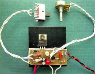
The board is designed to install fixed resistors. P1-4, C2-33, ceramic capacitor K10-17 (C1) and oxide TK series from Jamicon (the rest), TL431CLP microcircuits in the TO-92 package. The terminals of the LM317T (DA2) stabilizer are soldered on the side of the printed conductors, after which it is fixed with a screw and nut on a heat sink with an area of at least 100 cm2 (Fig. 3).
To avoid short circuits, an insulating gasket made of thin plastic is placed between it and the board, which is glued with epoxy glue to the board and heat sink. The device assembled and tested in operation is placed in a plastic case of suitable dimensions, on the wall of which the SA1 switch (for example, SPl 12-DP3T, SLF-2301-7R), the SB1 button (any small-sized self-returning one, for example, PKN159) and the variable resistor R4 are mounted (SPZ-46M). Opposite the HL1 LED, a hole is drilled in the wall. Instead of the KT361B transistor, any KT208, KT209, KT361, KT3107 series can be used in the device, instead of KP303B - a transistor of this series with indices A, B and G. We can replace the AL307BM LED with any one with a forward voltage of 1,8 ... 2,5 V and sufficient the brightness of the glow at a current of 2 ... 3 mA. Establishment begins with measuring the discharge current in various positions of the SA1 switch. To do this, the device is connected through a milliammeter with a measurement limit of 0 ... 5 A to an adjustable power source with an output voltage of about 5 V and a load current of at least 500 mA. The exact values of the discharge current are set by a selection of resistors R6-R8 (starting from the first). The variable resistor R4 is provided with a scale, which is graduated as follows. By connecting the device and a voltmeter with the appropriate measurement limit to the output of an adjustable power source and moving the slider of the resistor R4 to the lower (according to the diagram) position, turn on the source and set the voltage at its output, to which it is permissible to discharge this battery during operation. Then they briefly press the SB1 button and, slowly turning the slider, make the HL1 LED go out, after which they make an appropriate mark on the scale, similarly put marks on the scale corresponding to the values of the discharge voltage of other batteries. Author: I. Nechaev, Moscow
Machine for thinning flowers in gardens
02.05.2024 Advanced Infrared Microscope
02.05.2024 Air trap for insects
01.05.2024
▪ Smartphones charge faster and understand voice ▪ Photo recognition determines your exact location ▪ RPS-30/45/65 - compact medical power supplies ▪ Promising material for lithium-ion batteries
▪ section of the site Dosimeters. Selection of articles ▪ article Music plays, standard jumps. Popular expression ▪ article Who Invented the Elevator? Detailed answer ▪ article Guarantees of workers' rights to labor protection ▪ stun gun article. Encyclopedia of radio electronics and electrical engineering ▪ article Arrow indicators. Encyclopedia of radio electronics and electrical engineering
Home page | Library | Articles | Website map | Site Reviews
www.diagram.com.ua |


 Leave your comment on this article: