|
|
ENCYCLOPEDIA OF RADIO ELECTRONICS AND ELECTRICAL ENGINEERING Charger and power supply with advanced operational capabilities. Encyclopedia of radio electronics and electrical engineering
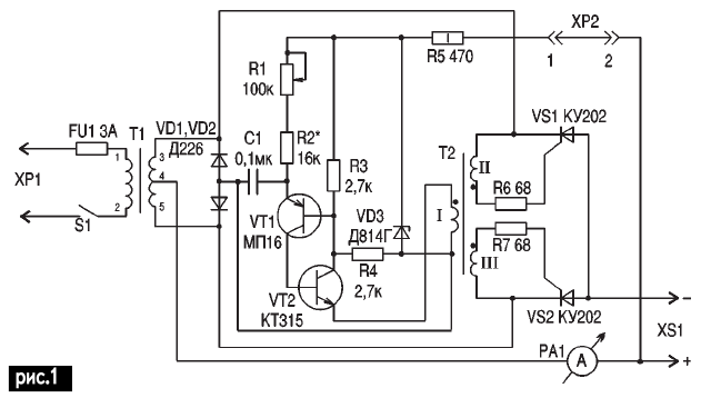
Encyclopedia of radio electronics and electrical engineering / Chargers, batteries, galvanic cells When developing the circuit of the charger-supplying device (ZPU), the following tasks were set: to increase the efficiency through the use of pulse regulation; ensure smooth adjustment of the output current; apply a simple element base; reduce the number of power elements; simplify the design; equip with simple service devices that increase the operational capabilities of the ZPU, which could be gradually added to the main circuit without significant modifications. Scheme (Fig. 1) It is an adjustable full-wave rectifier based on a trinistor regulator with pulse-phase control, where trinistors VS1 and VS2 are used as power controlled diodes. A detailed description of the principles of operation of the regulator, possible options for circuitry, replacement of elements are described in detail in [1]. Particular attention must be paid to the accuracy of manufacturing T2. The edges of the ring should be blunted, and the ring itself should be wrapped around the diameter with two layers of electrical tape to avoid closing the windings II and III through the core. The T2 transformer is made on a K20x10x11 2000NN ferrite ring and contains 3x75 turns of PEV-2 wire with a diameter of 0,22 mm. The winding is made with a bundle of three wires, which is technologically convenient when connecting and phasing the T2 windings (Attention! If windings II and III are accidentally connected during installation, then twice the rectifier voltage will be applied to T2 through them and T2 will fail). The beginnings of the windings (indicated in Fig. 1 by a dot) are connected to the emitter VT2, RE VS1 and VS2, and the ends of the corresponding windings are connected to the anodes VD1, VD2 and cathodes VS1, VS2. Structurally, the trinistors are placed on one radiator with an area of 300 mm2 without insulating gaskets (you can use the ZPU case). If the charger is used carefully and accurately, controlling the degree of charge of the battery (battery) using an additional voltmeter connected to the XS1, then you can use the ZPU according to Fig. 1. But since his "majesty the case" is predicted by the algorithm - there are no accidents - there are natural patterns, it is better to equip the ZPU with devices that exclude the failure of the ZPU, or connect a battery to it under the following external negative influences:
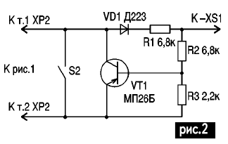
The scheme for finalizing the ZPU is shown in Fig. 2 (with the structure of Fig. 1 + Fig. 2). It is a transistor switch controlled by the magnitude and polarity of the input voltage (on the battery) and controlling the supply voltage of the phase-pulse generator, connected instead of the XP2 jumper.
With a heavily sulphated battery, it is possible that the polarity at the terminals of a correctly connected battery will be opposite, or the battery is highly discharged, and the voltage on it is less than the opening voltage of the transistor switch. In both cases, the ZPU will not work. To eliminate this, the S2 toggle switch was introduced, with which the key is shunted for some time to achieve the necessary polarity and voltage on the battery to hold the key in the open state and normal charging process. After that, the toggle switch is opened. In [2], this is not taken into account, and the ZPU will not work. When using the details shown in Fig. 2, the circuit does not need to be adjusted. In practice, when it is necessary to use vehicles in the winter, and the return of the battery (in terms of capacity) with a decrease in temperature is greatly reduced, and the battery is already being operated "twice or three times higher than the norm" (the volume of the active mass has decreased due to natural shedding, and the battery itself The battery is heavily sulphated, which led to an even lower return on capacity and an increase in internal resistance), it is impossible to reliably start the car. In many ways, you can get rid of these problems, as well as increase the life of the battery when the car is in the garage, and the battery is constantly connected to the ZPU, which operates in the "standby" mode and maintains it in full readiness for operation. According to the recommendations contained in [4], the battery life can be extended up to 5-6 years when applied to the battery "from the early days" of the standby mode (in storage)! (instead of 1-2!), and in other cases, significantly slow down the destructive processes occurring in the battery during operation. It has proved itself well in practice by the simplicity of circuitry, element base and configuration of the circuit (made both in combination with the ZPU, and as a prefix to the already existing ZPU), shown in Fig. 3, recommended [3] (according to the structure of Fig. 1 + Fig. 2+fig.3) connected to XS1.
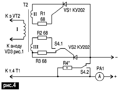
The circuit is an electronic relay with separately adjustable on and off thresholds. It is energetically more profitable than the scheme in [2], since T1 is disconnected from the network for the duration of the "standby" mode, which can reach several hours of pause for several minutes of charging. The scheme is not critical to the applied details. It is desirable to use silicon transistors, resistor values R1, R4-R6 ± 20%, R2, R3 - trimming wire type SP5-1, since they allow you to set the threshold with an accuracy of ± 0,1 V and keep the tuning stable over time. The Zener diode VD2 is a thermally compensated precision type D818E, although two Zener diodes of the D814 type, connected towards each other, with approximately the same stabilization voltage, can also be used. Setting up the "standby" mode node is carried out as follows. The potentiometer slider R2 is set to the upper position, and the slider R3 is set to the lower position (according to the diagram). Connector XP1 is not connected to the network. A stabilized power supply with regulated voltage is connected to the XS1 connector, which is set to 1 V by a reference voltmeter connected to XS14,5. In this case, the transistors VT1 and VT2 must be closed, and the relay K1 is de-energized. By rotating the engine R3, relay K1 is activated. Then the voltage of the stabilized source is reduced to 12,9 V and the relay is released by rotating the R2 slider. Due to the fact that when the relay K1 is released, the resistor R2 is closed by the contacts K1.2, these adjustments are independent of each other. The resistances of resistors R1 and R4 are designed for an interval of 12,9-14,5 V. For other threshold values, they must be re-selected. Relay K1 - any, reliably operated from 12 V, with two groups of breaking contacts, allowing switching power of 200-300 W, PCM1 (Yu.171.81.43); PCM3 (RF4.500.129); RES6 (RFO.452.125.D); RES22 (RF4.500.129 - contacts connected in parallel). If there are no relays recommended above, then you can rewind any. For example, the relay operates at a voltage of 60 V and a current of 0,02 A, has a switching power of 60x0,02 = 1,2 W, 1200 turns of wire D0,1 mm, the number of turns per 1 V = 1200: 60 = 20, wire cross section S \u4d pDD: 3 \u14d 0,1, 0,1x4x0,00785: 2 \u12d 12 mm20. We need a relay that operates on a voltage of 240 V. The number of turns of the rewound relay is 5x60 = 12. Since the operation voltage has decreased by a factor of 5 (2:0,00785), it means that the current (at the same switching power) must increase by a factor of 5. To provide the same current density in (A / mm0,4), it is necessary to increase the cross section (not the diameter!), Of the wire, i.e. 2x4=8 mm4. From where D \u0,4d 3,14S / p0,23 \u240d 0,23xXNUMX: XNUMX \uXNUMXd XNUMX mm. This means that the rewound relay has XNUMX turns of XNUMX mm wire. To slow down the process of sulfation and automatic "training" of the battery during the "standby" mode in the winter (charging with asymmetric current), the circuit according to Fig. 1 can be converted by turning off the trinistor VS2 and connecting the discharge resistor R1 (Fig. 4) toggle switch S4.
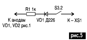
The ratio of charging and discharging currents is 10:1, and the magnitude of the charging current is determined by the rated current of the battery being charged. To avoid recharging the battery in a pulse, it must be remembered that in the circuit according to Fig. 4, the charge is carried out by half-wave pulses with a frequency of 50 Hz, and the discharge occurs during a pause between pulses. Therefore, the ZPU ammeter will show the average charge current, approximately three times less than the current in the pulse. For example, according to the recommendation [5], a battery with a capacity of 55 Ah must be charged with a current of 1,8 A. When using the scheme according to the structure of Fig. 1 + Fig. 2 + Fig. 3 + Fig. 4, the total charge time in the "standby" mode compared to circuit according to the structure of Fig.1 + Fig.2 + Fig.3 will increase, and the discharge time will decrease. In addition, the ZPU turns into a charger-power-discharge device with a discharge current of 1/100 of the battery capacity. It is better to adjust the asymmetry using an oscilloscope connected in parallel with a 0,1 Ohm resistor connected in series with an active load (you can use a lamp from a headlight) according to a 10:1 ratio of the charge and discharge voltage amplitudes (proportional to currents). If there is no oscilloscope, the asymmetry can be adjusted with a tester. For example, for a 6ST55 battery, the charging current is set by resistor R1 equal to 1,98 A (1,8 + 0,18). The load is turned off without changing the position of the resistor R1 slider, the discharge resistor R4 is connected to the ZPU (Fig. 5) and the discharge current is set to 0,18 A by selecting its resistances. When the LHP operates on an active load (electric vulcanizer, incandescent lamp, etc.), the load voltage may exceed 14,5 V, and the LHP will turn off, which is not taken into account in [3]. To eliminate this, the S3.1 toggle switch is used, which disconnects the circuit according to Fig. 3 from + XS1 and at the same time S3.2 connects the VD1R1 circuit (Fig. 5), through which the opening voltage from the anodes VD1 and VD1 is supplied to the VT2 base (Fig. 1 ).
The introduction of this chain is due to the need to protect the ZPU from a short circuit in the power supply mode when operating on all other types of loads, except for the battery. The transformer can be used ready-made, from tube TVs, leaving only the primary winding and winding the secondary according to Table 1. If there is a transformer with a geometry different from that given in the table, you can use the recommendations [4]. To charge a battery with a capacity of 40-60 Ah, a current of 1-2 A is sufficient, and an increase in the charging time does not play a role, since when using automatic control of the charging time is not required. Table 1
Therefore, for the manufacture of T1 ZPU, a transformer from 50 W (empirically 5 cm2) is suitable, which provides about 21 V at a current of 1-2 A on the II winding. The calculation of T1 can be made according to [7] or practically determine the number of turns per 1 V by the test winding method according to [6]. During prolonged operation in the "standby" mode, it is necessary to control the electrolyte level in the battery by periodically adding distilled water. There is no need to use a filter for noise suppression, since T1 also acts as a filter. References:
Author: S.A. Elkin
Machine for thinning flowers in gardens
02.05.2024 Advanced Infrared Microscope
02.05.2024 Air trap for insects
01.05.2024
▪ Hyperloop overclocked to 1019 km / h ▪ Sewing machine with computer ▪ 10-storey house built in a day ▪ Revealed the secrets of children's memory
▪ section of the site Lecture notes, cheat sheets. Selection of articles ▪ article by Shirley MacLaine. Famous aphorisms ▪ article Who Invented the Airplane? Detailed answer ▪ Article Four-loop knot. Travel Tips
Home page | Library | Articles | Website map | Site Reviews www.diagram.com.ua |


 Arabic
 Bengali
 Chinese
 English
 French
 German
 Hebrew
 Hindi
Hindi Italian
 Japanese
 Korean
 Malay
Malay Polish
 Portuguese
 Spanish
 Turkish
 Ukrainian
 Vietnamese


 Leave your comment on this article: