Two voltages from one source. Encyclopedia of radio electronics and electrical engineering

Encyclopedia of radio electronics and electrical engineering / Power Supplies
 Comments on the article
Sometimes, to power various radio devices, it is required to have two bipolar voltages of +12 and -12 V (or +9 and -9 V) from one source - a battery or a mains transformer with one winding. Such voltages are necessary for the operation of operational amplifiers and some other circuits. In this case, the main current consumption by the circuit is carried out, as a rule, along a circuit with a positive voltage, and the "-" circuit is auxiliary.
The industry produces a specialized converter chip for obtaining a negative voltage: KR1168EP1 (input voltage 3 ... 10 V, and the output negative is the same value as at the input). But it is not yet widely available, and also covers a narrow voltage range.

Rice. 5.4 (click to enlarge)
On fig. 5.4 shows a diagram of a simple converter that allows you to receive an additional stabilized voltage of -12 V (-9 V when using the KR12EN9A stabilizer) from a +142 V (+8 V) source. The load current in the -12V circuit can be up to 15 mA.
The converter operates at a frequency of 50 kHz and remains operational when the supply voltage drops to 7 V.
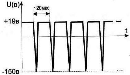
Fig. 5.5

Rice. 5.6. The design of the transformer T1
The circuit consists of a self-oscillator on a transistor VT1, a voltage-up transformer T1 and an integrated stabilizer DA1.
When assembling, it is required to observe the polarity of the connection of the phases of the windings of the transformer T1, indicated in the diagram. From the secondary winding of the transformer, the voltage after rectification should be 15 ... 19 V, which is necessary for the normal operation of the DA1 stabilizer.
To configure the converter, first, instead of DA1, we connect a 150 Ohm resistor. During normal operation of the circuit, the voltage shape on winding 3 in transformer T1 is shown in fig. 5.5, When setting up, it may be necessary to select the capacitor C3 and the resistor R2.
Transformer T1 is made on an armored core of size B22 made of ferrite 2000NM (1500NM) and contains 1 - 80 turns, 2 - 15 turns, 3-110 turns of PELSHO-0,18 wire in the winding (Fig. 5.6). After checking and adjusting the circuit, fix the coil and ferrite cups with glue.
Capacitors C2, C4, C5 used type K50-29-63V, C1 and C3 - any small-sized, C6 - K53-1A-20V.
All elements of the circuit are placed on a printed circuit board with dimensions of 65x50 mm (Fig. 5.7). To reduce the height of the board, the installation is made in two levels - capacitors C4 and C5 are located above the elements VT1 and DA1. The circuit allows you to get a higher output voltage than at the input, if you use a negative voltage spike (Fig. 5.5).
If the device you have assembled is stationary and can be powered from the mains, then widely used small-sized transformers (designed in the form of a mains plug) can be used to obtain a bipolar voltage. They have one secondary winding, and in order not to rewind the transformer, it is convenient to use the circuit (Fig. 5.8).

Rice. 5.7. Converter printed circuit board

Fig. 5.8
Publication: cxem.net
 See other articles Section Power Supplies.
Read and write useful comments on this article.
<< Back
 Latest news of science and technology, new electronics:
Machine for thinning flowers in gardens
02.05.2024
In modern agriculture, technological progress is developing aimed at increasing the efficiency of plant care processes. The innovative Florix flower thinning machine was presented in Italy, designed to optimize the harvesting stage. This tool is equipped with mobile arms, allowing it to be easily adapted to the needs of the garden. The operator can adjust the speed of the thin wires by controlling them from the tractor cab using a joystick. This approach significantly increases the efficiency of the flower thinning process, providing the possibility of individual adjustment to the specific conditions of the garden, as well as the variety and type of fruit grown in it. After testing the Florix machine for two years on various types of fruit, the results were very encouraging. Farmers such as Filiberto Montanari, who has used a Florix machine for several years, have reported a significant reduction in the time and labor required to thin flowers.
... >>
Advanced Infrared Microscope
02.05.2024
Microscopes play an important role in scientific research, allowing scientists to delve into structures and processes invisible to the eye. However, various microscopy methods have their limitations, and among them was the limitation of resolution when using the infrared range. But the latest achievements of Japanese researchers from the University of Tokyo open up new prospects for studying the microworld. Scientists from the University of Tokyo have unveiled a new microscope that will revolutionize the capabilities of infrared microscopy. This advanced instrument allows you to see the internal structures of living bacteria with amazing clarity on the nanometer scale. Typically, mid-infrared microscopes are limited by low resolution, but the latest development from Japanese researchers overcomes these limitations. According to scientists, the developed microscope allows creating images with a resolution of up to 120 nanometers, which is 30 times higher than the resolution of traditional microscopes. ... >>
Air trap for insects
01.05.2024
Agriculture is one of the key sectors of the economy, and pest control is an integral part of this process. A team of scientists from the Indian Council of Agricultural Research-Central Potato Research Institute (ICAR-CPRI), Shimla, has come up with an innovative solution to this problem - a wind-powered insect air trap. This device addresses the shortcomings of traditional pest control methods by providing real-time insect population data. The trap is powered entirely by wind energy, making it an environmentally friendly solution that requires no power. Its unique design allows monitoring of both harmful and beneficial insects, providing a complete overview of the population in any agricultural area. “By assessing target pests at the right time, we can take necessary measures to control both pests and diseases,” says Kapil ... >>
| Random news from the Archive Climate weapons against weather anomalies
24.07.2017
The Boulder National Center for Atmospheric Research, having studied the trend of a constantly deteriorating climate on Earth, proposed to cope with the problem created by leading states "climate weapons".
Rising greenhouse gas concentrations, forest fires and melting polar ice have already led to irreversible consequences that can still be eliminated.
In the fight against abnormal weather conditions, which will soon become the norm, discoveries in the field of geoengineering will help. Scientists propose to put their developments in the service of humanity, since, according to available data, greenhouse gases will change the world temperature by 2040 ° C by 2, as a result of which extreme weather anomalies await the inhabitants of the planet, which have not yet been observed in history.
The researchers propose spraying sulfates into the atmosphere to trap the sun's rays and cool the Earth. A method called "chemtrails" or "paths in the clouds" is able to balance climate change and contain the onset of the catastrophic effects of global warming.
During the Vietnam War, Phantom C-130s and F-4s sprayed silver iodide into rain clouds, resulting in heavy rainfall.
|
Other interesting news:
▪ Climate neutral arena
▪ First anion in space
▪ Revealed the secret of dog friendliness
▪ Quiet New Fujitsu Celsius Workstations
▪ Magnetic heads polished with green tea
News feed of science and technology, new electronics
 Interesting materials of the Free Technical Library:
▪ section of the site History of technology, technology, objects around us. Article selection
▪ article A sultry woman is a poet's dream. Popular expression
▪ article How can you tell a carnivore from a herbivore by eye position? Detailed answer
▪ Article Kupena officinalis. Legends, cultivation, methods of application
▪ article Ionizer ION-1. Encyclopedia of radio electronics and electrical engineering
▪ article Smart magnetic goose. physical experiment
Leave your comment on this article:
 All languages of this page
Home page | Library | Articles | Website map | Site Reviews

www.diagram.com.ua
2000-2024


 Arabic
 Bengali
 Chinese
 English
 French
 German
 Hebrew
 Hindi
Hindi Italian
 Japanese
 Korean
 Malay
Malay Polish
 Portuguese
 Spanish
 Turkish
 Ukrainian
 Vietnamese