|
|


 Arabic
 Bengali
 Chinese
 English
 French
 German
 Hebrew
 Hindi
Hindi Italian
 Japanese
 Korean
 Malay
Malay Polish
 Portuguese
 Spanish
 Turkish
 Ukrainian
 Vietnamese
|
ENCYCLOPEDIA OF RADIO ELECTRONICS AND ELECTRICAL ENGINEERING Powerful voltage converter for car amplifier. Encyclopedia of radio electronics and electrical engineering
Encyclopedia of radio electronics and electrical engineering / Voltage converters, rectifiers, inverters Currently, a huge range of radio tape recorders of different price categories is presented on the automotive equipment market. Modern car radios usually have 4 line outputs (some still have a separate subwoofer output). They are designed to be used "head" with external power amplifiers. Many radio amateurs make power amplifiers with their own hands. The most difficult part in a car amplifier is the voltage converter (PV). In this article, we will consider the principle of building stabilized PNs based on the already "popular" TL494 microcircuit (our analogue of KR1114EU4). Control Node Here we will take a very detailed look at the operation of the TL494 in stabilization mode. The sawtooth voltage generator G1 serves as the master. Its frequency depends on the external elements of C3R8 and is determined by the formula: F=1/(C3R8), where F is the frequency in Hz; C3- in Farads; R8- in ohms. When operating in a push-pull mode (our PN will just work in this mode), the frequency of the self-oscillator of the microcircuit should be two times higher than the frequency at the output of the PN. For the ratings of the timing circuit indicated on the diagram, the generator frequency F = 1 / (0,000000001 * 15000) = 66,6 kHz. The output pulse frequency is roughly 33 kHz. The generated voltage is supplied to 2 comparators (A3 and A4), the output pulses of which are summarized by the OR element D1. Further, the pulses through the elements OR - NOT D5 and D6 are fed to the output transistors of the microcircuit (VT1 and VT2). Pulses from the output of the element D1 also arrive at the counting input of the trigger D2, and each of them changes the state of the trigger. Thus, if a logical "13" is applied to pin 1 of the microcircuit (as in our case, + is applied to pin 13 from pin 14), then the pulses at the outputs of elements D5 and D6 alternate, which is necessary to control a push-pull inverter. If the microcircuit is used in a single-cycle Pn, pin 13 is connected to a common wire, as a result, trigger D2 is no longer involved in the work, and pulses appear at all outputs simultaneously. Element A1 is an error signal amplifier in the output voltage stabilization circuit PN. This voltage is applied to pin 1 of node A1. On the second output - the exemplary voltage obtained from the stabilizer A5 built into the microcircuit using a resistive divider R2R3. The voltage at the output A1, proportional to the difference between the input, sets the threshold for the operation of the comparator A4 and, consequently, the duty cycle of the pulses at its output. The R4C1 chain is necessary for the stability of the stabilizer. Transistor optocoupler U1 provides galvanic isolation in the negative voltage feedback circuit. It refers to the output voltage stabilization circuit. Also, the stabilizer of the parallel type DD1 (TL431 or our analogue KR142EN19A) is responsible for stabilization. The voltage drop across resistor R13 is approximately 2,5 volts. The resistance of this resistor is calculated by setting the current through the resistive divider R12R13. The resistance of the resistor R12 is calculated by the formula: R12 \u2,5d (Uout-12) / I "where Uout is the output voltage of the PN; I" is the current through the resistive divider R13RXNUMX. The load DD1 is a parallel-connected ballast resistor R11 and a radiating diode (pin 1,2 of the optocoupler U1) with a current-limiting resistor R10. The ballast resistor creates the minimum load necessary for the normal functioning of the microcircuit. IMPORTANT. It should be taken into account that the operating voltage of the TL431 should not exceed 36 volts (see the datasheet on the TL431). If it is planned to manufacture a PN with Uout.> 35 volts, then the stabilization circuit will need to be changed a little, as will be discussed below. Suppose that the PN is designed for an output voltage of + -35 Volts. When this voltage is reached (on pin 1 of DD1, the voltage reaches a threshold of 2,5 Volts), the stabilizer DD1 will “open”, the LED of the optocoupler U1 will light up, which will lead to the opening of its transistor junction. At pin 1 of the TL494 chip, the level "1" will appear. The supply of output pulses will stop, the output voltage will begin to fall until the voltage at pin 1 of the TL431 is below the threshold 2,5 Volts. As soon as this happens, DD1 "closes", the LED of the optocoupler U1 goes out, a low level appears at pin 1 of the TL494 and node A1 allows the output pulses to be supplied. The output voltage will again reach +35 Volts. Again, DD1 will “open”, the LED of the optocoupler U1 will light up, and so on. This is called "duty cycle" - when the pulse frequency is unchanged, and the adjustment is carried out by pauses between pulses. The second error signal amplifier (A2) in this case is used as an input for emergency protection. This can be a control unit for the maximum heat sink temperature of the output transistors, a UMZCH protection unit against current overload, and so on. As in A1, through the resistive divider R6R7, the reference voltage is applied to pin 15. Pin 16 will have a "0" level, since it is connected to the common wire through resistor R9. If you apply a level "16" to pin 1, then node A2 will instantly disable the supply of output pulses. The PN "stops" and starts only when the level "16" appears again at pin 0. The function of comparator A3 is to ensure that there is a pause between pulses at the output of element D1., even if the output voltage of amplifier A1 is out of range. The minimum response threshold A3 (when pin 4 is connected to a common wire) is set by the internal voltage source GI1. With an increase in the voltage at pin 4, the minimum duration of the pause increases, therefore, the maximum output voltage of the PS decreases. This property is used for soft start PN. The fact is that at the initial moment of operation of the PN, the capacitors of the filters of its rectifier are completely discharged, which is equivalent to closing the outputs to a common wire. Starting the PN immediately at full power will lead to a huge overload of the transistors of the powerful cascade and their possible failure. The C2R5 circuit provides a smooth, overload-free start-up of the PN. At the first moment after switching on, C2 is discharged., And the voltage at pin 4 of TL494 is close to +5 Volts received from the A5 stabilizer. This guarantees a pause of the maximum possible duration, up to the complete absence of pulses at the output of the microcircuit. As the capacitor C2 is charged through the resistor R5, the voltage at pin 4 decreases, and with it the duration of the pause. At the same time, the output voltage of the PN increases. This continues until it approaches the exemplary one and the stabilizing feedback comes into effect, the principle of which was described above. Further charging of the capacitor C2 does not affect the processes in Stump. As already mentioned here, the operating voltage of the TL431 should not exceed 36 volts. But what if it is required to receive, for example, 50 volts from the PN? Make it simple. It is enough to put a 15 ... 20 Volt zener diode into the break of the controlled positive wire (shown in red). As a result of this, it will "cut off" the excess voltage (if a 15-volt zener diode, then it will cut off 15 volts, if a twenty-volt one, then it will accordingly remove 20 volts) and the TL431 will operate in an acceptable voltage mode.
Based on the foregoing, a PN was built, the scheme of which is shown in the figure below.
An intermediate stage is assembled on VT1-VT4R18-R21. The task of this node is to amplify the pulses before they are fed to powerful field-effect transistors VT5-VT8. The REM control unit is made on VT11VT12R28R33-R36VD2C24. When a control signal from the radio +12 Volts is applied to "REM IN", the transistor VT12 opens, which in turn opens VT11. A voltage appears on the VD2 diode, which will power the TL494 chip. Mon starts. If the radio is turned off, then these transistors will close, the voltage converter will "stop". On the elements VT9VT10R29-R32R39VD5C22C23, an emergency protection unit is made. When a negative pulse is applied to the "PROTECT IN" input, the PN will turn off. It will be possible to start it only by re-disabling and enabling REM. If this node is not planned to be used, then the elements related to it will need to be excluded from the circuit, and pin 16 of the TL494 chip will be connected to a common wire. In our case, the PN is bipolar. Stabilization in it is carried out according to the positive output voltage. So that there is no difference in output voltages, the so-called "DGS" is used - a group stabilization choke (L3). Both of its windings are wound simultaneously on one common magnetic circuit. Get a choke-transformer. The connection of its windings has a certain rule - they must be turned on in the opposite direction. In the diagram, the beginnings of these windings are shown with dots. As a result of this inductor, the output voltages of both arms are equalized. An important role in Stump is played by snubbers - an RC chain, which serves to bypass parasitic RF / microwave oscillations. Their use favorably affects the overall operation of the converter, namely: the output signal shape has fewer parasitic RF emissions that penetrate the power supply into the UMZCH and can cause its excitation; the output keys work easier (they heat up less), this also applies to the transformer. The benefits of them are obvious, so that they should not be neglected. On the diagram, this is C12R26; C13R27; C25R37. Establishment Before switching on, it is necessary to check the quality of the installation. To establish a PN, a transformer power supply unit with a capacity of about 20 Amperes and with an output voltage regulation limit of 10 ... 16 Volts is required. It is not recommended to power the PN from a computer power supply. Before turning on, you need to set the output voltage of the power supply to 12 volts. In parallel with the output of the PN, connect resistors for 2 W 3,3 kOhm both to the positive shoulder and to the negative one. Unsolder the PN resistor R3. Apply power supply from the PSU to the PN (12 Volts). Mon should not start. Next, you should apply a plus to the REM input (put a temporary jumper on the + and REM terminals). If the parts are in good condition and the installation is done correctly, then the PN should start. Next, you need to measure the current consumption (ammeter in the gap of the positive wire). The current must be within 300 ... 400 mA. If it is very different upwards, then this indicates that the circuit does not work correctly. There are many reasons, one of the main ones is the transformer is not wound correctly. If everything is within acceptable limits, then you need to measure the output voltage both positively and negatively. They should be almost the same. The result is memorized or written down. Next, in place of R3, you need to solder a series chain of a constant resistor of 27 kOhm and a trimmer (can be variable) of 10 kOhm, not forgetting to first turn off the power from the PN. Let's start PN again. After starting, we increase the voltage on the power supply to 14,4 volts. We measure the output voltage of the PN in the same way as during the initial switch-on. By rotating the axis of the tuning resistor, you need to set the output voltage, which was when the power supply was from 12 volts. After turning off the PSU, unsolder the series resistor circuit and measure the total resistance. In place of R3, solder a constant resistor of the same rating. We do a control check. The second option for building stabilization The figure below shows another option for building stabilization. In this circuit, not its internal stabilizer is used as a reference voltage for pin 1 of the TL494, but an external one, made on the TL431 parallel type stabilizer. Chip DD1 stabilizes the voltage of 8 volts to power the divider, consisting of a phototransistor optocoupler U1.1 and resistor R7. The voltage from the middle point of the divider is supplied to the non-inverting input of the first error signal amplifier of the TL494 SHI controller. The output voltage of the PN also depends on the resistor R7 - the lower the resistance, the lower the output voltage. The PN setting according to this scheme does not differ from the one in Figure No. 1. The only difference is that initially you need to set 8 volts at pin 3 of DD1 using the selection of resistor R1.
The voltage converter circuit in the figure below is distinguished by a simplified implementation of the REM node. Such a circuit solution is less reliable than in previous versions.
Details As a choke L1, you can use Soviet DM chokes. L2- self-made. It can be wound on a ferrite rod with a diameter of 12 ... 15mm. Ferrite can be broken off from the line transformer TVS by grinding it on carbon to the required diameter. It's long, but effective. It is wound with PEV-2 wire with a diameter of 2 mm and contains 12 turns. As a DGS, you can use the yellow ring from a computer power supply.
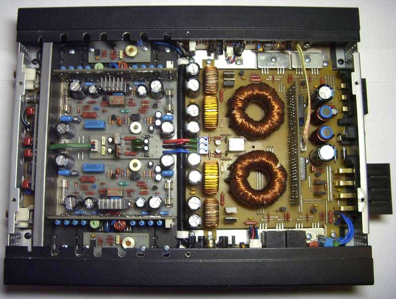
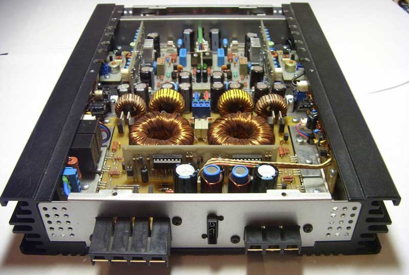
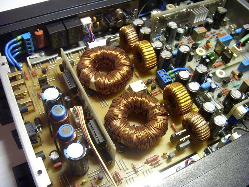
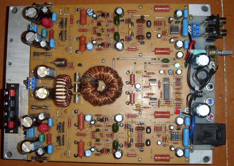
The wire can be taken PEV-2 with a diameter of 1 mm. It is necessary to wind two wires simultaneously, placing them evenly around the entire ring turn to turn. Connect according to the diagram (the beginnings are indicated by dots). Transformer. This is the most important part of the PN, the success of the entire enterprise depends on its manufacture. As a ferrite, it is desirable to use 2500NMS1 and 2500NMS2. They have a negative temperature dependence and are designed for use in strong magnetic fields. In extreme cases, you can use the M2000NM-1 rings. The result will not be much worse. Rings need to be taken old, that is, those that were made before the 90s. And even then, one party can be very different from the other. So, a PN whose transformer is wound on one ring can show excellent results, and a PN whose transformer is wound with the same wire, on a ring of the same size and marking, but from a different batch, can show a disgusting result. Here's how you get in. For this, there is an article on the Internet "Bald Calculator". With it, you can choose the rings, the frequency of the CG and the number of turns of the primary. If a ferrite ring 2000NM-1 40/25/11 is used, then the primary winding must contain 2 * 6 turns. If the ring is 45/28/12, then, respectively, 2 * 4 turns. The number of turns depends on the frequency of the master oscillator. Now there are many programs that, according to the entered data, will instantly calculate all the necessary parameters. I use rings 45/28/12. As a primary, I use a PEV-2 wire with a diameter of 1 mm. The winding contains 2 * 5 turns, each half-winding consists of 8 wires, that is, a "bus" of 16 wires is wound, which will be discussed below (I used to wind 2 * 4 turns, but with some ferrites I had to raise the frequency - by the way, this can be done by reducing resistor R14). But first, let's focus on the ring. Initially, the ferrite ring has sharp edges. They need to be ground off (rounded off) with a large emery or file - as it is more convenient for someone. Next, wrap the ring with molar white paper tape in two layers. To do this, we unwind a piece of adhesive tape 40 centimeters long, glue it on a flat surface and cut strips 10 ... 15 mm wide with a blade along the ruler. With these stripes we will isolate it. Ideally, of course, it is better not to wrap the ring with anything, but to lay the windings directly on the ferrite. This will favorably affect the temperature regime of the transformer. But as they say, God saves the safe, so we isolate him. On the resulting "blank" we wind the primary winding. Some radio amateurs first wind the secondary, and only then the primary on it. I haven't tried it so I can't say anything good or bad about it. To do this, we wind a regular thread on the ring, evenly placing the calculated number of turns around the entire core. We fix the ends with glue or small pieces of masking tape. Now we take one piece of our enameled wire and wind it along this thread. Next, take the second piece and wind it evenly next to the first wire. We do this with all the wires of the primary winding. The end result should be a smooth line. After winding, we call all these wires and divide them into 2 parts - one of them will be one half-winding, and the other will be the second. We connect the beginning of one with the end of the other. This will be the middle terminal of the transformer. Now we wind the secondary. It happens that the secondary winding, due to the relatively large number of turns, cannot fit in one layer. For example, we need to wind 21 turns. Then we proceed as follows: in the first layer we will place 11 turns, and in the second - 10. We will no longer wind one wire, as was the case with the primary, but immediately "tire". The wires should be laid so that they fit snugly and there are no loops and "lambs". After winding, we also call half-windings and connect the beginning of one to the end of the other. In conclusion, we dip the finished transformer into varnish, dry, dip, dry, and so on several times. As mentioned above, a lot depends on the quality of the transformer. Almost every person who makes a car amplifier with PN calculates boards for strictly defined dimensions. To make it easier for him, I present the printed circuit boards of master oscillators in the Sprint Layout-4 format. Download printed circuit boards Here are some pictures of PNs that were made according to these schemes:
Author: qwert390; Publication: cxem.net
Machine for thinning flowers in gardens
02.05.2024 Advanced Infrared Microscope
02.05.2024 Air trap for insects
01.05.2024
▪ Clothes with memory will adapt to the owner ▪ Huawei 40W 12000mAh Power Bank ▪ Photonic crystal invisibility cloak ▪ Solar mounting structures made from recycled wind turbine blades
▪ section of the site Car. Article selection ▪ article Tests and objectivity. The art of audio ▪ article CTO. Job description ▪ article Thermostable pulse generator. Encyclopedia of radio electronics and electrical engineering
Comments on the article: Nikita Super [;)]
Home page | Library | Articles | Website map | Site Reviews
www.diagram.com.ua |


 Leave your comment on this article: