|
|
ENCYCLOPEDIA OF RADIO ELECTRONICS AND ELECTRICAL ENGINEERING Economical power supply. Encyclopedia of radio electronics and electrical engineering
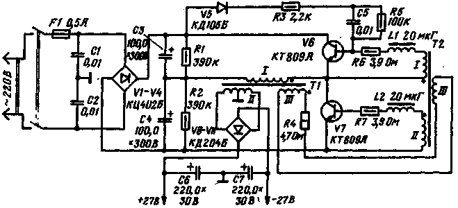
Encyclopedia of radio electronics and electrical engineering / Power Supplies Reducing the weight and dimensions and increasing the efficiency of power sources is one of the urgent tasks in the design of modern electronic equipment. The easiest way to solve this problem is to replace the traditional rectifier (with a mains transformer and capacitive filter) with a high-frequency converter, followed by rectification of the high-frequency voltage. Such power supplies, due to the fact that the voltage conversion occurs at a relatively high frequency (10 ... 40 kHz), have transformers and the entire structure of much smaller sizes and hence a higher power density, reaching up to 200 ... 400 W / cu. dm, which is several times more than traditional power supplies. A schematic diagram of such a power supply is shown in the figure. At the output of the block, a bipolar voltage of 2x27 V is obtained at a load current of up to 0,6 A. The amplitude of the output voltage ripple at the maximum load current does not exceed 30 mV. The mains voltage rectifier is assembled on diodes V1-V4. The rectified voltage converter is made on transistors V6, V7 and transformers T1 and T2, and the increased frequency voltage rectifier is made on diodes V8-V11. The operating frequency of the voltage converter is 22 kHz. Capacitors C1 and C2 are necessary to protect the mains from interference; arising during the operation of the converter. Resistors R1 and R2, together with capacitors C3C4, are the primary filter and at the same time a voltage divider for the converter. Chain V5. R3, C5, R5 is used to facilitate the start of the converter generator. - Capacitors C6, C7 serve as a filter for the rectified high-frequency voltage. The use of two transformers in the voltage converter made it possible to increase its efficiency. In conventional converters with one transformer, the latter operates in saturation mode. In a converter with two transformers, the output transformer T1 operates in a linear mode at much lower inductances than in a single-transformer converter. This makes it possible to reduce losses in the core and, consequently, to increase the efficiency of the converter. Saturable transformer T2 is designed only for the power consumed by the base circuits of transistors V6 and V7 and therefore has a small size. In converters with a single transformer, a significant surge of collector current appears at the moment of switching of transistors. In a converter with two transformers, this surge is practically absent, which significantly reduces the so-called dynamic losses and increases the overall efficiency of the converter. The presence of a connection between the transformers through the windings III leads to the fact that at the right time the transformer T2 enters the saturation mode. This is necessary in order to fulfill the operating conditions of the converter, which were mentioned above. Transformer T2 is a switching element included in the base circuits of transistors V6 and V7. When the transformer T2 is saturated, its magnetizing current increases rapidly, as a result of which the voltage drop across the resistor R4 increases, and the voltage across the winding III decreases, and consequently, on the windings I and II, which leads to a decrease in the base current and the output of an open transistor into the active region and switching transistors. The switching frequency is determined by the magnetization reversal time of the core of the saturable transformer T2. Inductors Dr1 and Dr2 provide a delay in opening one transistor until then. until the other is completely closed. This is necessary to eliminate through currents and reduce losses when switching transistors.
The data of transformers and chokes are placed in the table. A properly assembled power supply does not require adjustment. Author: V. Tsikulsky, Ternopil; Publication: N. Bolshakov, rf.atnn.ru
Machine for thinning flowers in gardens
02.05.2024 Advanced Infrared Microscope
02.05.2024 Air trap for insects
01.05.2024
▪ Microsoft contact lenses measure blood sugar ▪ An implant to connect the brain to a computer ▪ Ultra-budget smartphone Infinix Smart 7 HD ▪ The mechanism of aging of the immune system has been discovered
▪ site section Preamplifiers. Article selection ▪ article Serpent-tempter. Popular expression ▪ article Where do they pay and greet with rain? Detailed answer ▪ article Cameraman of the department of creative programs. Job description ▪ article Unusual Isotron Antenna. Encyclopedia of radio electronics and electrical engineering
Home page | Library | Articles | Website map | Site Reviews www.diagram.com.ua |


 Arabic
 Bengali
 Chinese
 English
 French
 German
 Hebrew
 Hindi
Hindi Italian
 Japanese
 Korean
 Malay
Malay Polish
 Portuguese
 Spanish
 Turkish
 Ukrainian
 Vietnamese

 Leave your comment on this article: