|
|


 Arabic
 Bengali
 Chinese
 English
 French
 German
 Hebrew
 Hindi
Hindi Italian
 Japanese
 Korean
 Malay
Malay Polish
 Portuguese
 Spanish
 Turkish
 Ukrainian
 Vietnamese
|
ENCYCLOPEDIA OF RADIO ELECTRONICS AND ELECTRICAL ENGINEERING Automatic staircase lighting control with motion sensor. Encyclopedia of radio electronics and electrical engineering
Encyclopedia of radio electronics and electrical engineering / Lighting The devices that control the lighting of the stairs in the house are not new and have been described many times in the literature and on the Internet. The author offers his own version based on the ready-made HC-SR501 module with a pyroelectric motion sensor. There is enough information on the Internet about its characteristics, and often quite contradictory. In view of this, in order to obtain plausible information about the capabilities of the module, its characteristics had to be rechecked partly by experience, partly by analyzing the circuit. As a result, the author came to the following values (however, they can be confidently attributed to only one instance of the module that was tested):
The module has a "night" mode of operation, but for this you need to install a photoresistor in it. On the Internet, you can find information about the operability of the HC-SR501 module at a supply voltage of 20 ... 30 V. This is not true, since an oxide capacitor with a nominal voltage of 16 V is installed at its power input. Therefore, it is reasonable to power it with a voltage of no more than 12 V . The microcircuit used in the module generates an alarm signal at its output in three-volt logic levels. But a 1,5 kΩ resistor is connected between its output and the OUT terminal of the module, so the module's load capacity is very small. In the single operation mode, after the first detection of an object moving in the sensitive zone, the logic voltage level at the module output becomes high and remains high for 5...250 s (the hold time is set during adjustment), other detections possible during this period are ignored. After the hold time has elapsed, the output level returns to low, but the next detection becomes possible only after the sensor properties are restored (this time is called "dead"). In the cyclic triggering mode, after the first motion detection, the output of the module is also set to a high level for the hold time, however, further triggers that occurred before the expiration of this time start its countdown again. As a result, the output level remains high until the duration of the pause between successive motion detections exceeds the hold time. On the photographs of the module, which can be found on the Internet, the "MD" jumper is visible, by rearranging which the operation modes are switched. However, in the module that the author has, only the place for its installation is indicated, and the printed conductors are separated so that the module always operates in the cyclic operation mode.
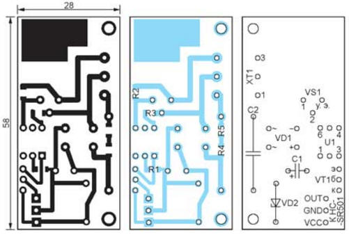
The "night" mode of operation means blocking the operation of the module during daylight hours. This useful feature allows you to save both electricity and the resource of light sources. To implement it, it is necessary to solder a photoresistor into the holes marked on the module board as "RL" (Fig. 2). The author could not find any data on its characteristics and mode features, however, the installation of a GL5516 photoresistor with a dark resistance of about 500 kOhm gave a completely satisfactory result. The module stopped working during daylight hours, so further research in this direction was not carried out.
The HC-SR501 module has greatly facilitated the creation of a staircase lighting control machine. Only a light source switch and a power node had to be added to it. It was decided to build the switch on a triac, which made the device more compact, reliable and silent compared to an electromagnetic relay. Considering that the own current consumption of such a device is small, a transformerless circuit was chosen for the power supply unit. This made it possible to reduce the overall dimensions of the device, the schematic diagram of which is shown in Fig. 3. It is powered by a 230 V, 50 Hz network, consuming mainly reactive, not counted by household meters, power of about 5 V-A, and is capable of switching lamps with a total power of up to 200 W.
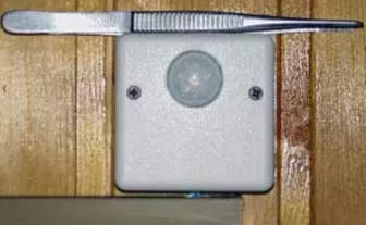
The transformerless power supply unit (C2, VD1, VD2, c1) generates a constant voltage of 5 V. The lighting lamp switch is built on a triac VS1 controlled by a triac optocoupler Ul. The optocoupler, in turn, controls the output signal of the HC-SR501 module. But the module cannot directly control the optocoupler, since the minimum current of the emitting diode of the optocoupler, at which its phototriac opens, is 5 mA, and the load capacity of the module output is much lower. Therefore, the emitting diode is connected to the module through an emitter follower on the VT1 transistor, which provides the necessary current amplification. The triac BTA1-08 used as VS800 can switch a much more powerful circuit than indicated above. But for this, it would have to be installed on a heat sink, the place for which is not provided in the author's version of the design due to the limited dimensions of the case. All parts of the machine, with the exception of the HC-SR501 module, are placed on a printed circuit board measuring 58x28 mm (Fig. 4), to which the module is connected by three wires. The board is designed for the installation of resistors for surface mounting, size 1206. The rest of the parts are in the usual design. The oxide capacitor C1 is "laid" on the board and glued to it. Capacitor C2 - K73-17 with a rated constant voltage of 630 V or similar imported. Three-pin screw block X11 for connecting the mains supply and luminaire EL1 - DG301 -5.0-03P-12. The whole device, the appearance of which is shown in Fig. 5 is housed in a standard 515x66x66mm G30B case.
To implement the "night mode" (if necessary), remove the Fresnel lens from the module board (it is very easy to do this), insert the photoresistor leads into the "RL" holes and solder them, then install the Fresnel lens back. But the photoresistor should be soldered only after the adjustment and adjustment of the device is completed, otherwise these operations will have to be carried out in the dark, which is very inconvenient. Since all elements of the described device are under mains voltage, when working with it with the case open, you must follow the rules of electrical safety. It is advisable to turn on the device for the first time without the HC-SR501 module, which will protect this module from damage in case of incorrect operation of the power unit. After connecting the device to the network, first of all check the voltage on the capacitor C1, which should be within 5,1 ± 0,3 V. After 20 ... 30 s, disconnect the device from the network and evaluate the temperature of the VD2 zener diode case. It may be slightly warm. Strong heating of the zener diode case indicates an incorrect choice of capacitance or a malfunction of capacitor C2. Next, connect a 1 V incandescent lamp to contacts 3 and 1 of the XT230 block. Plug the device into the mains and wait 20...40 seconds for the transients in the module to complete (at this time, the lamp may sometimes light up). Then bring a moving object into the module's sensitivity zone, for example, just wave your hand near it - the lamp should turn on. If this is the case, everything is working fine. If not, the reasons may be: - the current of its emitting diode is insufficient to open the phototriac of the optocoupler U1. It must be at least 7 ... 8 mA and can be set by selecting the resistor R1;
After completing the test, use the trimming resistors of the HC-SR501 module to set the required detection range (right, according to Fig. 2) and the alarm hold time (left, according to Fig. 2). It is recommended to adjust the detection range by installing the device at its permanent location in order to take into account the possible influence of surrounding objects on its operation. After completing the adjustment, install a photoresistor in the HC-SR501 module, if necessary, to ensure its operation in the "night" mode. PCB file in Sprint Layout 5.0 format: ftp://ftp.radio.ru/pub/2017/01/stairs.zip. Author: A. Savchenko
Machine for thinning flowers in gardens
02.05.2024 Advanced Infrared Microscope
02.05.2024 Air trap for insects
01.05.2024
▪ The deadly danger of ordinary dust
▪ section of the site Visual illusions. Article selection ▪ article Dual images. Encyclopedia of visual illusions ▪ article Where and when could you buy a rocking bath? Detailed answer ▪ article Silk knot. Travel Tips ▪ Article Cosmetics. Simple recipes and tips ▪ article Sim-Reader v.3. Encyclopedia of radio electronics and electrical engineering
Home page | Library | Articles | Website map | Site Reviews
www.diagram.com.ua |


 Leave your comment on this article: