|
|


 Arabic
 Bengali
 Chinese
 English
 French
 German
 Hebrew
 Hindi
Hindi Italian
 Japanese
 Korean
 Malay
Malay Polish
 Portuguese
 Spanish
 Turkish
 Ukrainian
 Vietnamese
|
ENCYCLOPEDIA OF RADIO ELECTRONICS AND ELECTRICAL ENGINEERING Convenient switch. Encyclopedia of radio electronics and electrical engineering
Encyclopedia of radio electronics and electrical engineering / Lighting Many are familiar with this situation: a long corridor, a switch at the front door. Coming home in the evening, turn on the light and take off your outer clothing. Then you turn off the light and go into the room, bumping into various objects in the dark, or you go into the room, turn on the light and, leaving the door open, return to the front door and turn off the light in the corridor. Both options are very inconvenient. Various two-switch circuits published in amateur radio literature require intervention in the wiring, which is not always acceptable.
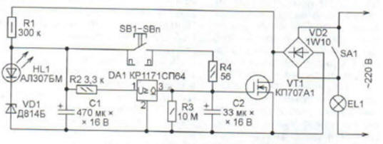
The proposed device, the scheme of which is shown in the figure, significantly increases the ease of use of lighting. The machine is connected in parallel to the standard switch SA1 of the lighting lamp EL1 (it can be several lamps connected in parallel). In the initial state, the capacitor C2 is discharged, the transistor VT1 is closed, a current of about 1 mA flows through the lamp EL1, determined by the resistance of the resistor R1. Capacitor C1 is charged to a voltage equal to the sum of the stabilization voltage of the Zener diode VD2 and the direct voltage drop across the HL1 LED. When you press any of the parallel-connected buttons SB 1-SBn, the capacitor C2 is charged from C1. Resistor R4 limits the charging current, which increases the durability of the button contacts. In this case, the rate of rise of the gate-source voltage of the transistor VT1 is quite large, which reduces the energy loss in the transistor channel when it is opened. As soon as the voltage across capacitor C2 becomes greater than the threshold voltage of transistor VT1, it will open. Thanks to the VD2 diode bridge, both half-waves of the EL1 lamp current pass through the open transistor, it shines in full heat. After releasing all the pressed buttons, the capacitor C2 begins to discharge through the resistor R3. After a few minutes, the voltage across the capacitor becomes less than the threshold voltage of the transistor VT1. The transistor closes, turning off the lamp EL1. The device returns to its original state. This time is enough to take off outerwear and walk down the corridor, or, conversely, walk down the corridor and put on outerwear. For longer lighting use switch SA1. In the first version of the device, which worked flawlessly for about a year, controlling an EL1 fluorescent lamp with an electronic ballast (electronic ballast), there was no resistor R2 and a voltage drop detector DA1. But when the fluorescent lamp was replaced with a conventional 60 W incandescent lamp, when the latter was turned off, the VT1 transistor overheated and failed. The point turned out to be that the voltage at the gate of this transistor drops very slowly (this is required to obtain a long exposure). For several seconds, it passes an interval near the cutoff voltage of the field-effect transistor, in which the resistance of its channel is already far from the minimum, but it is not yet completely closed. Since the electronic ballast of a fluorescent lamp contains a generator, the oscillations of which break down even with a relatively small decrease in the supply voltage, the lamp goes out at this moment and stops consuming current. Transistor VT1 does not have time to get very hot. And the incandescent lamp, as the resistance of the transistor channel increases, goes out gradually. The power dissipated by the transistor in this mode can exceed a quarter of its power. This is where it overheats. When finalizing, the fact was used that the capacitor C1, after opening the transistor VT1, is discharged through this transistor and resistor R1, as well as by the input current of the voltage drop detector DA1. If the duration of its discharge is less than the discharge of the capacitor C2 through the resistor R3, then by the time the voltage on the capacitor C1 drops below the detector threshold, the voltage on the capacitor C2 has not yet reached the dangerous zone. The opened output circuit of the detector will rapidly discharge this capacitor, ensuring the rapid closing of the transistor VT1. To obtain the desired ratio of time constants, the capacitance of the capacitor C2 had to be significantly increased. The device is assembled on a section of the universal breadboard and placed in the mounting box of the standard switch. Capacitors are used imported as the most compact. Any diode bridge can be used with a reverse voltage of at least 400 V and a rectified current of 1 A, for example, DB107, RS107, or it can be assembled from separate diodes with the same parameters. The field effect transistor must be with a permissible drain-source voltage of at least 400 V and a pulsed drain current of 10 A, for example, IRF840 or KP707 with any letter index. With a power of controlled lamps up to 200 W, the transistor does not require a heat sink. Zener diode D814D can be replaced by any low-power voltage 8 ... 11 V. Buttons SB1-SBn - from apartment calls. One of them is located in close proximity to the SA1 switch, the rest are installed in the required places. The switch does not require adjustment, only by selecting the capacitor C1 set the required duration of the lighting after the button is released. By placing the buttons appropriately, this device can be used to control staircase lighting. Author: K. Moroz
Machine for thinning flowers in gardens
02.05.2024 Advanced Infrared Microscope
02.05.2024 Air trap for insects
01.05.2024
▪ Project Jacquard for creating electronic clothing
▪ site section Parameters of radio components. Article selection ▪ article Skate like cheese in butter. Popular expression ▪ article What is metal? Detailed answer ▪ article Examination of insured events in connection with an occupational disease ▪ article Guessing the planned time. Focus secret
Home page | Library | Articles | Website map | Site Reviews
www.diagram.com.ua |

 Leave your comment on this article: