|
|
ENCYCLOPEDIA OF RADIO ELECTRONICS AND ELECTRICAL ENGINEERING Compressor for lighting installation. Encyclopedia of radio electronics and electrical engineering
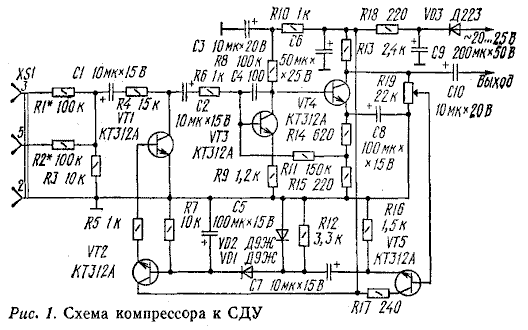
Encyclopedia of radio electronics and electrical engineering / Color and music settings It is known that the operation of a light-dynamic installation (SDU) becomes more effective if the range of brightness variation of the screen lamps is close to the range of variation of the input signal. Therefore, to match the dynamic ranges at the input of the CDS, it is necessary to turn on a device that "compresses" the dynamic range of the signal. Such a device is called a compressor. The effect of compression can also be achieved through feedback from optical devices or the use of lamps designed for different powers and voltages, or a special design of the screen device. As a rule, these methods are ineffective or significantly complicate the design and adjustment of the CDS. They are applicable only in specific CDS with a certain scheme and design. The use of compressors at the input of the CDS, built on the principle of an amplifier with deep AGC, when a weak signal is amplified, and a strong one is limited in amplitude or changes in its level are brought into line with a change in the brightness of the incandescent lamps of the screen device, is preferable. A diagram of such a compressor, tested with many SDUs, is shown in fig. 1.
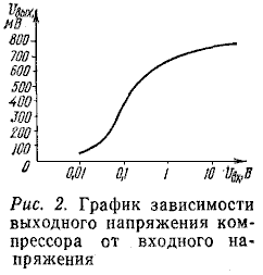
The gain of the device is independent of the frequency of the input signal. The shape of the output voltage in the frequency range of 30 Hz ... 20 kHz is sinusoidal. A graph of the dependence of the output signal level on the input level applied to the capacitor C1 is shown in fig. 2. The output voltage of the compressor can be changed using the trimmer resistor R19. When the resistor slider is in the upper position according to the circuit, the output signal level is 120 ... 720 mV when the input level changes from 30 mV to 3 V or otherwise - a change in the input signal level of 40 dB corresponds to a change in the output signal of about 15 dB. When the input signal changes from 30 mV to 10 V (about 50 dB), the output level changes by 16 dB. Such a change in the signal at the SDU input is quite consistent with the dynamic range of the brightness of incandescent lamps, which does not exceed 10...15 dB. For normal operation of some CDS, including the industrial set "Prometheus-1", an input signal level of 1 ... 2 V is required. When working with such CDS, moving the R19 slider down the circuit, you can increase the compressor output voltage to 2.. .2,5 V. In this case, the compression depth decreases somewhat (by 5...6 dB), but does not reduce the compressor efficiency. A load (SDU input) with a resistance of at least 3 kOhm is connected to the compressor output. The compressor input is connected to both mono and stereo sources of musical programs (tape recorder, electric player, radio receiver). Since the input impedance of the compressor is relatively high (about 100 kOhm), the signal can be taken not only from the outputs to the acoustic systems, but also from the line outputs of these devices. From the output of the source of musical programs, the signal goes to the resistive mixer R1-R3, which sums the signals of the left and right channels in stereo mode. At the same time, the mixer plays the role of a divider, which allows you to filter out extraneous noise and pickup signals, for example, those that occur during the operation of EPU engines, a tape recorder, or from the movement of the pickup needle along the plate. As a rule, these noises are less than the minimum volume music signal. However, without a divider, due to the high sensitivity of the compressor, they can be amplified by it to a value that the screen device of the CDS can respond to. At the same time, the use of the divider R1-R3 made it possible to increase the sensitivity of the compressor to 200 mV, which corresponds to the voltage at the linear outputs of sound reproducing devices.
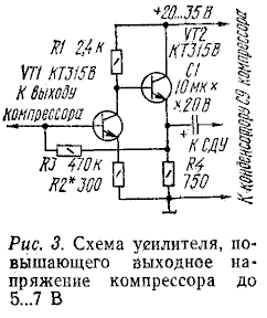
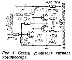
From the resistor R3, the audio frequency voltage is supplied through the capacitor C1 to the controlled divider R4VT1, in which the transistor is used as a voltage-controlled resistor. Next, the signal is fed to an amplifier made on transistors VT3 and VT4. Its gain is about 100. From the load of the amplifier (resistor R13), the signal is fed through the capacitor C10 to the SDU. At the same time, part of the amplified signal taken from the resistor R19 engine is fed to the cascade with the VT5 transistor. From the emitter of this transistor, the signal is fed to a detector made on diodes VD1, VD2. The constant voltage formed on the capacitor C5 is used to control the transistor VT1 (through the emitter follower on the transistor VT2). Any increase in the input signal level leads to an increase in the positive voltage on the capacitor C5 and a greater opening of the transistors VT1 and VT2. The resistance of the collector-emitter section of the transistor VT1 decreases, which means that the signal level on it also decreases. If the level of the compressor output signal is not enough for normal operation of the CDS, then to increase it to 5...7 V, an additional amplifier is connected between the CDS input and the compressor output, the circuit of which is shown in Fig. 3. The signal level at the SDU input can be changed by selecting the resistance of the resistor R3 in the amplifier and the tuning resistor R19 of the compressor. The amplifier is designed to work with SDU with an input impedance of at least 1 kOhm. With a lower input impedance of the SDU, and also if there is a matching transformer at the input of the SDU, an amplifier should be used, the circuit of which is shown in Fig. 4. If a signal of 3 ... 0,5 V is sufficient for the operation of CDS with an input resistance of several hundred ohms to 0,6 kOhm, then it can be supplied from the emitter of the transistor VT5 of the compressor, while excluding the resistor R19, connecting the base transistor VT5 with the collector of the transistor VT4 and soldering the positive terminal of the capacitor C10 from the collector of the transistor VT4 to the emitter VT5. KT312V, G; any diodes of the series D315, D9 (VD10, VD1), D2, D223, KD226 (VD103). Capacitors C3, C3-K10-53, K1-53; C4-KD-4, the rest - K1-50. Fixed resistors - MLT-6 or MLT-0,25, trimmer - SPZ-0,125. Under these parts, a printed circuit board (Fig. 16) made of one-sided foil fiberglass is calculated. Capacitor C5 (it eliminates the excitation of the compressor at high frequencies) is installed on the side of the printed conductors. Resistors R4 - R1 are soldered directly to the terminals of the XS3 connector.
Diode VD3 and capacitor C9 are installed at the location of the elements of the main power supply unit of the SDU. If the SDU itself is powered by a constant voltage of +24 ... 30 V, it can be supplied to the compressor by excluding the VD3 diode and capacitor C9.
The adjustment of the compressor begins with checking the absence of self-excitation at high frequencies and, if it exists, increase the capacitance of capacitor C4. Then, by applying a 1 V audio frequency signal to the compressor input, the desired voltage (19 ... 0,7 V) is set at the compressor output with a tuning resistor R2,5.
Finally, set the sensitivity of the device. By connecting it to a signal source, resistors R1 and R2 are selected such that the previously set output signal level is maintained at the required minimum signal level at the XS1 connector. Author: A. Anufriev; Publication: cxem.net
Energy from space for Starship
08.05.2024 New method for creating powerful batteries
08.05.2024 Alcohol content of warm beer
07.05.2024
▪ SAFT lithium batteries for extreme temperatures
▪ section of the site Electrical safety, fire safety. Article selection ▪ article Radio-controlled aerobatic model. Tips for a modeler ▪ article Two-channel combination lock. Encyclopedia of radio electronics and electrical engineering
Home page | Library | Articles | Website map | Site Reviews www.diagram.com.ua |


 Arabic
 Bengali
 Chinese
 English
 French
 German
 Hebrew
 Hindi
Hindi Italian
 Japanese
 Korean
 Malay
Malay Polish
 Portuguese
 Spanish
 Turkish
 Ukrainian
 Vietnamese


 Leave your comment on this article: