|
|


 Arabic
 Bengali
 Chinese
 English
 French
 German
 Hebrew
 Hindi
Hindi Italian
 Japanese
 Korean
 Malay
Malay Polish
 Portuguese
 Spanish
 Turkish
 Ukrainian
 Vietnamese
|
ENCYCLOPEDIA OF RADIO ELECTRONICS AND ELECTRICAL ENGINEERING Command apparatus for Signal-1. Encyclopedia of radio electronics and electrical engineering
Encyclopedia of radio electronics and electrical engineering / Radio control equipment For remote control of the Planet rover-7 children's toy, I used a self-made transmitter and receiver of the Signal-1 equipment, the description of which was in Radio, 1984, No. 6. But I connected an electronic command device to the receiver (see diagram in Fig. 1 ).
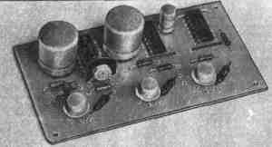
A clock generator is assembled on the elements DD1.1 and DD1.2, which generates pulses with a repetition rate of approximately 1 Hz (it depends on the capacitance of the capacitor C1 and the resistance of resistors R1 and R2). These pulses are fed to the synchronization input (C) of the DD2.1 trigger, which, together with the DD2.2 trigger, is a two-digit binary counter. Signal LEDs HL3 and HL4 are connected to the inverse outputs of the counter through resistors R1 and R2. They light up when these outputs have a logic level of 0. The direct outputs are connected to the information inputs (D) of the recording device, which is made on triggers DD3.1 and DD3.2. Transistor keys with electromagnetic relays are connected to the outputs of these triggers, as well as the inverter DD1.3, through resistors R7 - R9 - they switch the power circuits of electric motors of models M1 (left) and M2 (right). The synchronization inputs of triggers DD3.1 and DD3.2 are combined and connected through capacitor C2 to the output of the inverter assembled on the element DD1.3. The R6C3 chain is necessary to automatically set the triggers of the DD3 chip to the zero state after the power is turned on (by switch SA1). Capacitor C4, shunting the emitter junction of transistor VT3, is necessary to delay the operation of relay K3 when short command signals are applied. How does the command machine work? After turning on the power at the direct outputs (pins 5, 9) of the recorder triggers - logic 0 levels. The same signal is at the output of the element DD1.3. Therefore, transistors VT1 - VT3 are closed, the relays are released, the electric motors are de-energized. But the clock generator works and the LEDs light up in a binary code sequence. Consider the operation of the command device at the moment when the HL1 LED flashed. At the information input of the trigger DD3.1 (pin 2) - logic level 1, and at the information input of the trigger DD3.2 (pin 12) - the level of logic 0. If now the operator briefly (no more than 0,5 s) presses the power button of the transmitter , the transistor VT5 of the receiver will open and a logic level 1.3 will go to the input of the inverter DD0. A logic level 1 will appear at the output of the inverter. trigger input DD2 (pin 5). At the output of trigger DD3.1, a logic level of 1 will appear, and transistor VT1 will open. Relay K1 will work. With contacts K1.1, it will connect the terminals of the electric motor M1 to the power source GB2 in such polarity that the rover's caterpillar will begin to rotate forward. The model will turn to the right until the next command is received. If the operator holds the transmitter on button for more than 0,5 s, then relay K1 will work first, and then K3. KZ.1 contacts will disconnect the electric motor M1 from the power source and connect M2. The model will still turn to the right, but due to the rearward rotation of the right track. After releasing the button, relay K3 will release, and K1 will remain on. Instead of the right one, the left caterpillar will start to rotate. This is how the equipment works when the "Right" command is executed. To make the model turn left, you need to give a short or long pulse to turn on the transmitter at the moment when only the HL2 LED lights up. The "Forward" command is executed by pressing the transmitter button for a short time when both LEDs are lit, and the "Back" command is performed by pressing the button for a long time while the LEDs are off. If you give a short signal when the LEDs are off or a long one when they are on, the model will stop. Skills in managing a model equipped with this command apparatus. are acquired relatively quickly if you learn that a short command signal is stored and the corresponding command is executed by the model until the next one arrives, and with a long signal until the transmitter button is released. Moreover, in the latter case, the execution of the command that the recording device remembered will automatically continue. Instead of elements 2I-NOT of the K155LAZ microcircuit in the command device, you can use the elements AND-NOT, OR-NOT, NOT other microcircuits, for example, K155LA4. K155LE1, K155LE4, K155LN1. In addition to those indicated in the diagram, you can use DD2 K155TM7 in place, and K3TM155, K5TM155 in place DD7. K155TM8. Transistors - any, npn structures (MP37, KT315, KT3102). It is permissible to replace LEDs with incandescent lamps, say, MH 2,5-0,068, but they must be connected through transistor keys (pnp structure transistors) - similar to turning on a relay. A quenching resistor is connected in series with each lamp. Capacitors, resistors, diodes and switch - any type. Electromagnetic relays - RES9 passport RS4. 524.200, pre-finished. One group of relay contacts is removed, and in the remaining one, the fixed contacts are bent and the gap between the armature and the core of the magnetic circuit is reduced. As a result, the relay should operate at a small voltage. Other relays are suitable, with a response voltage of 3 ... 4 V and a current not exceeding the allowable current of the transistor collector. Power source GB1 - 3336 battery or three 343 cells connected in series. Some parts of the command device are mounted on a printed circuit board (Fig. 2) from one-sided foil fiberglass. The input terminals of the fourth element of the K155LAZ microcircuit are soldered to a common wire. The LEDs are mounted on the body of the model in a place convenient for observation, and electromagnetic relays are in close proximity to the electric motors.
To pre-test the operation of the command device, it is necessary to disconnect the terminals 9, 10 of the DD1.3 element from the collector of the transistor VT5 of the receiver and connect it through a 1 kΩ resistor to the plus of the power source, and between the terminals and the common wire, turn on the contacts of the push-button switch for short circuit. The GB2 source is turned off. After power is supplied by the switch SA1, the trimmer resistor R2 sets the required frequency of the clock generator (as the resistance of the resistor increases, the frequency decreases, and vice versa). By closing the contacts of the auxiliary push-button switch, the command signal is imitated and the operation of the electromagnetic relays is checked. Then the installation is restored and the joint operation of the receiver and transmitter is checked, as described in the "Establishment" section in "Radio", 1983, No. 12, p. 52. Now the receiver and the commander can be installed on the model and carry out sea trials by issuing commands over the radio. This command device can also be used with a receiver assembled according to the scheme in Radio, 1982, No. 8, p. 50. In this version, the receiver relay K1 is not used, and the collector of the transistor V3 is connected to the connection point of the capacitor C2 and the resistor R9 of the command device. Element DD1.3 is turned off and its inputs are connected to a common wire. Author: S. Rybaev, Kyiv; Publication: N. Bolshakov, rf.atnn.ru
Artificial leather for touch emulation
15.04.2024 Petgugu Global cat litter
15.04.2024 The attractiveness of caring men
14.04.2024
▪ Sony Cyber-shot DSC-WX500 and DSC-HX90V compacts ▪ Regular use of the touch screen of a smartphone affects brain function ▪ ASUS RP-AC87 Dual Band High Speed Repeater ▪ Computer reads minds in real time
▪ site section Clocks, timers, relays, load switches. Article selection ▪ article There are no free breakfasts. Popular expression ▪ article What is hemoglobin? Detailed answer ▪ celery article. Legends, cultivation, methods of application ▪ article Contest-RX radio receiver. Encyclopedia of radio electronics and electrical engineering
Home page | Library | Articles | Website map | Site Reviews
www.diagram.com.ua |

 Leave your comment on this article: