|
|


 Arabic
 Bengali
 Chinese
 English
 French
 German
 Hebrew
 Hindi
Hindi Italian
 Japanese
 Korean
 Malay
Malay Polish
 Portuguese
 Spanish
 Turkish
 Ukrainian
 Vietnamese
|
ENCYCLOPEDIA OF RADIO ELECTRONICS AND ELECTRICAL ENGINEERING Submersible electric pump control device. Encyclopedia of radio electronics and electrical engineering
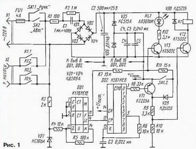
Encyclopedia of radio electronics and electrical engineering / Home, household, hobby When operating some household electrical appliances, a device that generates time cycles of turning them on and off can be useful. The author uses it with submersible pumps of the Malysh and Rucheek brands, but it is also useful for cyclic defrosting of the refrigerator and in other cases. The schematic diagram of the machine is shown in fig. 1. It consists of a network frequency divider, a time interval shaper, an actuator and an indicator.
The frequency divider is made on the K176IE12 chip [1] (DD1). Its clock input receives positive half-waves of the mains voltage limited by the R3VD7 circuit, from which rectangular pulses are formed by two inverters of the DD1 microcircuit and the R4R5 circuit. At the output of the divider (pin 4 of the DDI chip), the pulses have a repetition period of 655 s (or 10 min 55 s). This time interval determines the duration of the pause; the duration of the working cycle is set by the conversion factor of the DD2 microcircuit [2]. With the inclusion indicated in the diagram, this coefficient is equal to six, i.e., for one pause period there are five working periods with a total duration of 54 minutes 36 s, during which the pump will be turned on. The circuit for the initial installation of meters in order to simplify the circuit is not provided. The actuator is formed by an inverter on the transistor VT1. key on the transistor UT2 and relay K1. when triggered, the contacts K 1.1 - K 1.4 are closed, connecting the pump to the network. When operating in automatic mode, voltage pulses with a repetition period of 0.64 s with pin. 11 microcircuits DD1 through the resistor R7 enter the base of the transistor VT3 and. periodically opening it. make the HL1 LED blink. The SA1 toggle switch is used to turn on the pump manually. When its contact SA1.2 is closed, transistors VT2, VT3 open, the relay is activated and its contacts connect the pump to the network. In this mode, a constant current will flow through the HL1 LED, and it will glow without blinking. To power the machine, a source with a ballast capacitor C1, a rectifier on diodes VD1 - VD4 and a stabilizer on zener diodes VD5, VD6 was used. The machine is mounted on a printed circuit board made of foil fiberglass (Fig. 2). When assembling, resistors MLT-0,5 (R1 and R2J and MLT-0.125 (others) were used). Capacitor C1 - K73-17 (any other with the specified capacity and allowable voltage of at least 400 V will do); C2 - K50-6 ( its operating voltage should not be less than the total stabilization voltage of the VD5, VD6 circuit); the rest are K10-7, KM-6. The K561IE8 chip can be replaced with a similar one from the K176, 564 series. and VT1 must be with a permissible voltage UКe of at least 2 V. Rectifier diodes VD3 - VD30 must have a permissible reverse voltage of more than 1 V; LED - any type. The desired brightness of its glow can be set by selecting resistor R4.
Switches SA1, SA2 - any toggle switches with two groups of contacts that allow switching voltage of 250 V at a current of up to 2 A (for example, TP1 -2). Relay K1 - RES22 passport RF4.500.163. You can use a different type of relay, but it may be necessary to replace the VD5 zener diode, taking into account the operating voltage of the relay winding. For example, when using a relay with a winding for a voltage of 12 V, the zener diode KS515A (VD5) should be replaced with KS133A. In any case, the relay contacts must be designed for switching mains voltage at a current of up to 2 A. The device is mounted in a housing measuring 150x80x40 mm. Switches and an LED are placed on the end surface of the case. The fully assembled machine should be mounted on the body of the water dispenser or in another place convenient for use, which excludes the ingress of water into the device. A correctly assembled device starts working immediately after being turned on; the operation of the divider on the DD1 chip in automatic mode is controlled by the blinking of the KL1 LED. On the basis of the described device, devices for other purposes can also be made, for example, an automatic refrigerator defrost and a number of others. In this case, it may be necessary to change the ratio of the pulse duration and pause by using different outputs of the counter DD2. So when you connect the resistor R6 to output 2 (pin 4 DD2), the ratio is 1:1. to output 3 (pin 7 DD2) - 2:1, etc. With the maximum possible ratio of 9I, the R6C3 circuit should be excluded, and pin 15 DD2 connected to a common wire. To change the division factor, you can install a switch that connects the resistor R6 to one or another output of the counter DD2. The order of operation of the device can also be reversed (in this case, the working pulses will be several times shorter than the pauses). To do this, the VT1 transistor should be replaced with an n-p-n structure transistor, for example, on any KT315 or K503 series. switched on by an emitter follower (collector - to the + Upit circuit, emitter - to R9, VD9). The timing will remain the same. You can also cut all work cycles in half by connecting pin 13 of DD2 not to pin 4. but to pin 6 of the DD1 chip. In this case, the duration of the pause will be 5 min 28 s. the length of the working cycle will change accordingly. ATTENTION! The machine has a transformerless power supply, therefore, when testing and installing it, extra care should be taken. The metal case of the machine should be grounded (connected to the body of the water dispenser). It is better to use a plastic case. Power circuits must be phased in such a way that the circuit passing through the switches is connected to the mains phase conductor. The common wire of the device must not be connected to its body. Literature
Author: D. Nikishin, Kaluga
Machine for thinning flowers in gardens
02.05.2024 Advanced Infrared Microscope
02.05.2024 Air trap for insects
01.05.2024
▪ Lemon and sun for water disinfection ▪ Brown-eyed people are trusted more ▪ Motherboard Gigabyte G1.Sniper Z87 ▪ Miniature Bluetooth acceleration and temperature sensor based on CC2650
▪ site section Welding equipment. Article selection ▪ article by Wilhelm Schwebel. Famous aphorisms ▪ Deception Island article. Nature miracle ▪ article Automatic - LED switch. Encyclopedia of radio electronics and electrical engineering ▪ article I know your card. Focus secret
Home page | Library | Articles | Website map | Site Reviews
www.diagram.com.ua |

 Leave your comment on this article: