|
|


 Arabic
 Bengali
 Chinese
 English
 French
 German
 Hebrew
 Hindi
Hindi Italian
 Japanese
 Korean
 Malay
Malay Polish
 Portuguese
 Spanish
 Turkish
 Ukrainian
 Vietnamese
|
ENCYCLOPEDIA OF RADIO ELECTRONICS AND ELECTRICAL ENGINEERING Light day machine. Encyclopedia of radio electronics and electrical engineering
Encyclopedia of radio electronics and electrical engineering / Home, household, hobby One of the main conditions for successfully growing flowers and vegetables in greenhouses is compliance with the required light regime. It can be provided automatically by the device described in this article. In addition to greenhouses, it will be used for lighting aquariums, as well as in rooms where it is necessary to extend daylight hours, for example, in poultry houses and livestock farms. The proposed "Daylight" automatic switches on the lighting at dusk and turns it off when the programmed daylight time has expired. which, depending on the type of plant, can be adjusted from 12 to 15 hours at intervals of one hour. The schematic diagram of the "Daylight" machine is shown in Fig. 1. It consists of a master oscillator and a pulse repetition frequency divider on the DD1 chip, a frequency divider by 60 on the DD4 chip and a preset counter made on the DD6 chip, a pulse shaper on elements DD2.1, DD2.2 and a control unit.
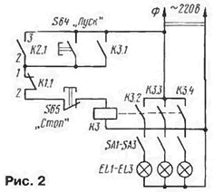
Daylight hours are programmed by setting the code on the DD6 meter. The minimum time is 12 hours (both switches in the position indicated in the diagram). This time can be increased by 1, 2 or 3 hours by turning on SB2 and (or) SB3. In reality, the time is 21 minutes less than indicated, since the first edge at the DD4 output occurs 39 minutes after the reset. After turning on the supply voltage at the input 9 of the element DD2.3 there will be a log level. 0, and at its output - the level of the log. 1, which resets the triggers DD5.1 and DD5.2 and pre-installs the counter DD6. The quartz oscillator and pulse frequency divider on the DD1 chip begin to work immediately after the supply voltage is applied to them. From pin 10 of the DD1 chip, pulses with a period of 1 minute are supplied to the input C of the 60 divider on the DD4 chip. However, the counter does not start counting yet, since at the R input of the DD4 microcircuit and at the PI transfer input of the DD6 counter from the pin. 2 triggers DD5.1 are supplied with an inhibiting log level. 1. At night, the resistance of the photoresistor R3 is greater than the resistance of the resistor R2, and therefore, at terminals 1, 2 of the DD2.1 element of the DD2 microcircuit, the voltage exceeds the microcircuit switching threshold, and at the counting input C of the DD5.1 trigger - log. 0. In the morning, when the illumination increases, the resistance of the photoresistor R3 decreases and the voltage at terminals 1.2 of element DD2.1 also begins to decrease. When it reaches the switching voltage of element DD2.1, the chain D02.1, DD2.2, DD2 4 switches to another state. This process is accelerated due to positive feedback through capacitor C3. Trigger DD5.1 switches, and a log appears at its inverse output. 0, which allows the operation of counters DD4 and DD6, and also prohibits the passage of pulses through element DD2.4. Every hour the status of counter DD6 will decrease by one. When the device is started, 4 is written to bits 8 and 6 of the DD1 counter. Inverted by the DD3.3 element, it prohibits the passage of pulses through DD3.1, and the DD5.2 trigger cannot change its state in the morning. After at least five hours, a log will appear at output 8 of DD6. 0, at input 2 DD3.1 - log. 1. It will allow the passage of pulses from the shaper DD2.1, DD2.2 to the input C of the trigger DD5.2. In the evening, when natural light decreases, the resistance of photoresistor R3 increases. Then on the output. 3 elements DD3.1 the log level appears. 0, and at the counting input 11 of the DD5.2 trigger - the log level. 1. As a result, the trigger will change its state and close the DD3.2 element for the passage of pulses. Further changes in the photo sensor illumination will not affect the operation of the machine until the set time has expired. After changing the trigger state to pin. 13 of element DD5.2 the log level will appear. 1, which will go to the differentiating chain C6R7. From the output of DD7.2, a pulse of 0,6 s duration will go through resistor R9 to the base of transistor VT2 and open it. Relay K2 will operate, and through its closed contacts K2.1, power will be supplied to the short-circuit starting relay (Fig. 2). When it is triggered, the short-circuit contacts will close. 1 - K3.4. Contact K3.1 blocks relay K3, and K3.2 - K3.4 (depending on the position of switches SA1-SA3) will connect one or another lighting line EL1 - EL3.
After the set number of pulses on the counter DD6 has been subtracted, a log will appear at its transfer output P. 0. A log will be supplied to the S input of the DD6 counter and the R inputs of the DD5.1 and DD5.2 flip-flops through the DD2.3 element. 1. This will preset the counter and reset the triggers. The differentiating chain C5R6 and inverters DD7.1, DD7.4 will generate a pulse to turn off the lighting, which will open transistor VT1. Relay K1 will operate, and the open contacts K 1.1 will de-energize the short-circuit relay. Its contacts K3.1 - K3.4 will open and the lighting will turn off. This will happen at night, and in the morning the machine’s operation cycle will repeat. When working in a greenhouse, sometimes it becomes necessary to extend the time the lighting is turned on; this can be easily done using the SB4 (“Start”) and SB5 (“Stop”) buttons. After completing the work and turning off the lighting, you must briefly press the SB1 ("Reset") button to set the machine to its original state. After installing the machine for the same purpose, you also need to press this button in the dark. During the day, in low light, the light can be turned on manually, but before leaving the greenhouse, if it is still light enough, it must be turned off. A Krona battery is used as a backup power source, connected to the main source through a diode VD1. With a current consumption in counting mode of about 0,5 mA (in relay operation mode - 20 mA), the backup battery is enough for the entire season of growing vegetables. It is better to place the photoresistor in a place in the greenhouse where moonlight and light from car headlights do not fall on it at night. Setting up the device begins with checking the functionality of the generator and pulse frequency dividers on the DD1 chip. This can be done even with an avometer by checking the presence of second pulses at pin 4 and minute pulses at pin 10 of the DD1 microcircuit. Next, check the signal at pin 4 of element DD2.2. To do this, cover photoresistor R3 from light and select the resistance of resistor R2 such that the log level is set at pin 4. 1. The resistance of resistor R2 depends on the selected illumination level at which the machine should operate. After this, you should open the jumper between contacts XT1 - XT2 and connect contact XT2 to the pin. 4DD1. If you have a frequency meter with a start-stop input, it should be connected to pin 9 of the DD4 chip, and the counting input to the XT2 contact. Then you need to turn on the table lamp and close the photoresistor from the light. At the end of the counting, the frequency meter should display a number equal to that set at the installation inputs of the DD6 counter and expressed in minutes. If the frequency meter does not have a start-stop input, its counting input is connected to pin 10 of the DD4 chip, but then the displayed number will be expressed in hours. In the absence of a frequency meter, at the moment the table lamp is turned on, you need to measure the time to the nearest minute, and then the number of minute pulses supplied to the DD6 counter must be equal to the number set in binary code at its setting inputs. To reliably determine the moment the meter stops (by eye), a red LED is connected in parallel to the winding of relay K1 through a 1 kOhm resistor. Having finished checking the functionality of the device, you should restore the jumper between contacts ХТ1-ХТ2. The machine is mounted on a printed circuit board made of foil fiberglass 1,5 mm thick with dimensions of 100x60 mm. Its views from the side of printed conductors and from the side of parts are shown in Fig. 3.
The device uses MLT-0,125 resistors. Capacitors C1 - C3, C5, C6 - KM-6, C4, C7 - K53-1. KT315B transistors are interchangeable with any low-power silicon p-pn structures with a permissible collector current of at least 100 mA. Instead of the K561IE11 (DD6) microcircuit, the K561IE14 is suitable (for counting in binary mode, its pin 9 must be connected to the +9 V circuit), K561LA7 (DD2, DD3. DD7) and K561TM2 (DD5) are interchangeable with similar K176 series microcircuits. Relay K1, K2 - RES49 passport RS4.569.426. Many years of their operation has shown stable operation in the machine. These relays can be replaced with RES32 passport RF4.500.341 or RES15 passport RS4.591.003. Switches SB1 - SB3 - P2K. Photoresistor R3 was used by the author from an OEP14 optocoupler, from which the light bulb was removed, and the photosensitive layer was filled with epoxy resin. The OEP14 optocoupler contains two photoresistors (pins 2,6 and 3,5), it is better to connect them in parallel. It is permissible to use any other photoresistor, providing for its adjustment (as mentioned above) by selecting the resistance of resistor R2. The connecting wire to the photoresistor, 1 m long, must be shielded. Quartz resonator ZQ1 - PK71, it can be replaced with any one from a faulty quartz clock, and if its frequency is two times lower, then pin. 7 DD1 chips should not be connected to pin. 4, and with pin. 6. The relay is attached to the board with two copper brackets, and the quartz resonator is installed through a rubber gasket. The board is best placed in a shielded case. Author: N.Zaets, Veydelevka settlement, Belgorod region.
Machine for thinning flowers in gardens
02.05.2024 Advanced Infrared Microscope
02.05.2024 Air trap for insects
01.05.2024
▪ The most annoying sound to the human ear ▪ Data transmission using fast neutrons ▪ Louis Vuitton bags with AMOLED screens ▪ Miniature rocket engine powered by water
▪ section of the site Metal detectors. Article selection ▪ article History of medicine. Lecture notes ▪ article Where can I buy baby condoms? Detailed answer ▪ article Open an empty jar. Focus Secret
Home page | Library | Articles | Website map | Site Reviews
www.diagram.com.ua |


 Leave your comment on this article: