|
|


 Arabic
 Bengali
 Chinese
 English
 French
 German
 Hebrew
 Hindi
Hindi Italian
 Japanese
 Korean
 Malay
Malay Polish
 Portuguese
 Spanish
 Turkish
 Ukrainian
 Vietnamese
|
ENCYCLOPEDIA OF RADIO ELECTRONICS AND ELECTRICAL ENGINEERING Economy timer. Encyclopedia of radio electronics and electrical engineering
Encyclopedia of radio electronics and electrical engineering / Clocks, timers, relays, load switches The proposed timer is an attempt by the author to find a compromise between the complexity of the device and its functionality. The problem was solved by making a relatively cheap PIC12C508A microcontroller use just one input and three output signals to control a multi-output LCD and determine the state of a large number of controls. The device is very economical and can work autonomously, beeping the end of the specified shutter speed. The control of an external actuator is also provided, from which the timer can also receive power. In the latter case, its capabilities are greatly expanded. The minimum exposure time is 1s, the maximum is 100 hours. Schematic diagram of the timer is shown in fig. 1. A crystal oscillator is assembled on the DD1.1 element. From the output of the DD1.2 element, which reduces the influence of the input circuit of the DD3 microcontroller on the generator (it is especially noticeable when the supply voltage is less than 3,5 V), a signal with a frequency of 32768 Hz is fed to the input of the timer / counter built into the DD3 microcontroller.
The codes of the program that should be entered into the memory of the microcontroller using the programmer are shown in the table. After turning on the power, acting on this program, it will configure the lines of its I / O port GP2 and GP3 to work as inputs, and GPO, GP1, GP4 and GP5 - outputs and put the built-in timer / counter into the pulse counting mode received at the input GP2. The countdown is based on interrupts generated when the counter overflows. Therefore, exposure accuracy does not depend on the stability of the 4 MHz clock generator built into the microcontroller.
At the output GP0, the microcontroller generates a signal intended for the common electrode (COM) of the LCD HG1. A 32-bit shift register on DD4-DD7 microcircuits is used to generate signals applied to the segments of all indicator digits, as well as polling signals for the SB1-SB 12 buttons and the S1 configuration switch. The codes required for this are sent in serial form to the input D of the DD4 microcircuit from the output GP1 of the microcontroller. At the output of GP4, they are accompanied by shift pulses. It should be noted that such an application of a shift register with a combination of the functions of controlling the indicator and polling the controls became possible due to the significant inertia of the LCD. Short-term "extra" pulses on its outputs do not cause distortion of the symbols displayed by the indicator. To poll the controls at the outputs of the shift register DD4-DD7, a "running zero" sequence is formed. As a result, in cycles corresponding to the pressed buttons or closed contacts of switch S1, the logic level at the GP3 input of the microcontroller is low, and in the rest it is high. At a low logic level at pin 10 of the DD6 microcontroller, the microcontroller analyzes the signal generated by the DA1 undervoltage detector and coming to the GP3 input through the elements DD1.3, DD1. 4 and diode VD3. The exposure end signal generated by the microcontroller at the GP5 output is fed to the device output (pin 2 of the XS1 socket) through the protective resistor R4. The same signal controls the generator on the DD2 chip, tuned to 4200 Hz - the resonant frequency of the HA1 piezoelectric emitter. As a result, the timer beeps. The sound can be turned off by closing contacts S1.7. In autonomous mode, the device is powered by a galvanic battery GB1. The winding of relay K1 is de-energized, and its open contacts K1.2 switch S1 (with the exception of the group of contacts mentioned above) is disconnected from the input of the microcontroller. This is done to reduce the current consumed by the device by approximately 0,5 mA, which in this case does not exceed! mA (plus another 2 mA when the sound generator is running). Savings cost - the timer works autonomously in a single mode: countdown time - in seconds, the signal about the end of the exposure - a continuous duration of 1 minute, before the expiration of which it can be stopped by pressing any button. Pressing the buttons in this mode is accompanied by short beeps. If you apply a voltage of 1 V from an external source to pins 3 and 1 of the XS5 socket, relay K1 will work, disconnecting the battery and connecting switch S1 to the microcontroller. Diodes VD1, VD2 reduce the voltage on the relay winding K1 to an acceptable value. They also prevent the timer from switching to external power if the polarity of the latter is reversed. Now, by closing contacts S1.1, you can count the time in minutes, and using S1.2 change its direction from reverse to direct (the indicator readings will increase during the counting process). The next four groups of contacts control the format of the end-of-exposure signal. S1.3 makes the signal continuous or intermittent, S1.4 removes or sets the signal duration limit, S1.5 inverts it (the beep, if enabled, will sound during the exposure and stop after it expires). And with closed contacts S1.6, the forced shutdown of the end of exposure signal will occur only with the start of a new cycle of its countdown by pressing the "Start" button. The assignment of contacts S1.7, which was mentioned above, remains unchanged. With the help of S1.8, the "soundtrack" of keystrokes and the corresponding short pulses on pin 2 of socket XS1 are turned off. Since the microcontroller analyzes the state of the switch S1 only once (immediately after turning on the power), in order to activate the changes made during the operation of the device, you need to turn off and then turn on the power. With external power, the audio signal generator is blocked by the open transistor VT1. If blocking is not necessary, the transistor and resistors R1 and R3 are not installed. Immediately after turning on the device, zeros are displayed in all digits of the indicator, and the decimal points are flashing, indicating that the timer is waiting for the shutter speed to be entered. After entering each digit, the dot in the corresponding digit stops flashing. Attempts to enter the numbers 6-9 in the third digit will remain unsuccessful. This must be a number not greater than 5. The maximum value that can be set (9959) is 99 min. 59 s or 99 h 59 min depending on the selected unit of account (second or minute). If an error is made during entry, press the SB 11 ("Set") button and enter the desired value again. The timer starts counting the shutter speed by pressing the SB12 ("Start") button. The fact that the countdown is in progress is evidenced by the value on the indicator changing once per second or minute and the dot continuously "running" through its digits. To stop the timer, just press the "Start" button again. With a running count, the device reacts only to it. "Set" button valid only when the account is stopped. If the supply voltage drops to 2,8 V before the end of the count, decimal points will be turned on in all digits of the indicator. When the count does not go, the inscription displayed on the indicator will warn about the voltage drop of the following
- stylized "low battery". The operation of the timer at a lower voltage is not guaranteed and depends on the properties of the microcircuits installed in it. The volume of the sound signal decreases sharply already at a voltage of 3,5 V.
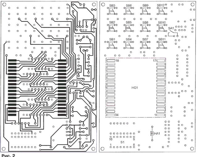
The timer is assembled on a double-sided printed circuit board. On fig. 2 shows its side, on which the indicator HG1, buttons SB1-SB12 (TS-A3PS-130 or similar), switch SA1 and sound emitter HA1 are placed. All other elements are installed on the reverse side, shown in fig. 3, and the GB1 battery (three AA batteries) is in a container outside the board.
Instead of the PIC12C508A microcontroller, the PIC12C508, PIC12C509 or PIC12C509A will fit without changing the program. Relay K1 - RES60, version RS4.569.435-04 or RS4.569.435-09. Quartz resonator ZQ1- in a small-sized cylindrical case. Please note that large resonators do not work well with a reduced supply voltage. When setting up the device, the constant resistor R8 is temporarily replaced with a variable value of 100 kOhm and with its help the frequency of the sound signal is selected at the maximum volume. By measuring the input resistance of the variable resistor, a constant value of the nearest value is set instead. For stable operation of the crystal oscillator over the entire range of supply voltage changes, it may be necessary to select the resistor R5. Author: A. Ermakov, Nizhny Novgorod
Air trap for insects
01.05.2024 The threat of space debris to the Earth's magnetic field
01.05.2024 Solidification of bulk substances
30.04.2024
▪ Nanocomposite on graphene and silicon will improve lithium-ion batteries ▪ Flexible electrically conductive ceramic paper ▪ Transcend USB 3.0 Flash Drives 128GB and 256GB
▪ section of the site Application of microcircuits. Article selection ▪ article Votes are weighed, not counted. Popular expression ▪ article What is an artesian well? Detailed answer ▪ article Working in sterilization rooms. Standard instruction on labor protection ▪ article Antenna current meter. Encyclopedia of radio electronics and electrical engineering
Home page | Library | Articles | Website map | Site Reviews
www.diagram.com.ua |


 Leave your comment on this article: