|
|


 Arabic
 Bengali
 Chinese
 English
 French
 German
 Hebrew
 Hindi
Hindi Italian
 Japanese
 Korean
 Malay
Malay Polish
 Portuguese
 Spanish
 Turkish
 Ukrainian
 Vietnamese
|
ENCYCLOPEDIA OF RADIO ELECTRONICS AND ELECTRICAL ENGINEERING Protection of the apartment with notification by telephone line. Encyclopedia of radio electronics and electrical engineering
Encyclopedia of radio electronics and electrical engineering / Security devices and object signaling The device is connected to the telephone line in parallel with the telephone set or according to the parallel telephone connection scheme and is designed to protect the apartment from penetration through windows or doors, depending on the installation location of the F1...Fn sensors. When an alarm sensor is triggered, neighbors or relatives are notified via a telephone line with a prearranged signal, and also turns on a siren or a bell for 3 minutes. If necessary, the number of the notified subscriber can be easily replaced by rearranging the jumpers in the dialing field. Compared to similar functions in phones with caller ID (the latest versions, such as "Rus" or "Vega"), this device has a lower cost, does not contain imported equipment, is easier to set up and more reliable in operation, and is also non-volatile from a 220 V network .
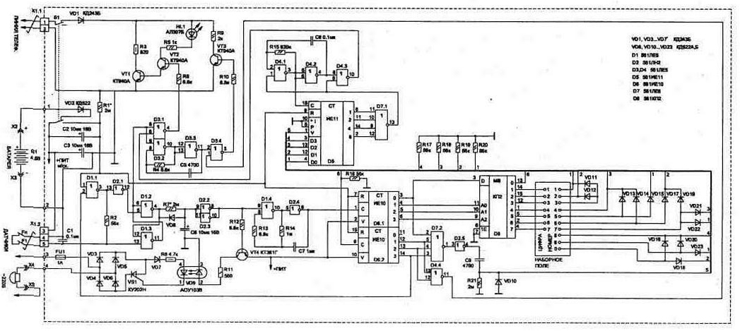
The electrical circuit of the device is assembled on easily accessible eight microcircuits of the MOS series (Fig. 3.1), and consists of the main nodes: shaper pulse dial telephone number on the elements D4.1...D4.3, D5, D7.1; a type-setting field, where it is installed by winding seven jumpers onto the contact pins (for setting up to seven digits of a fixed notification number); decimal to binary code converter on diodes VD11...VD23; time interval generator for operation of the entire device on elements D8, D6, D4.4, D7.2; security sensor actuation detector on D1.1...D1.3, D2.1, D2.2; tone generator D3.2, D3.4 and control stage on D3.1, VT1...VT3. The HL1 LED allows you to control the operation of the entire security device. It lights up when the telephone line is busy in the alarm mode and flashes at a frequency of 10 Hz when a number is dialed into the line. Dialing into the telephone line is performed by transistors VT1, VT2, which are controlled by a sequence of pulses from element D4.3 (controlled oscillator). The generator works in conjunction with the D5 counter, in the initial setting register of which the binary codes of the digits of the telephone number set by jumpers are sequentially written. Counter D5 starts to work on subtraction until the moment of time until all its outputs are set to logical "0". Logic "0" will then be set at the output D4.3 (pin D4/10). To turn on a bell or siren in the apartment, an AOU103V (VD9) optocoupler pair and a KU202N, M, K, L (VS1) thyristor are used, which provides electrical isolation of the telephone line from the 220 V network. The security device can be powered by any batteries or accumulators with voltage from 4,5 to 15 V and consumes microcurrent in standby mode (less than the self-discharge current of the batteries). If desired, the circuit can be supplemented with a device for automatically recharging the batteries from the telephone line when the security mode is triggered (Fig. 3.2).
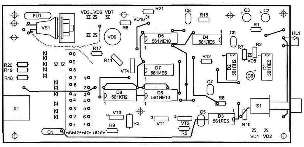
All construction details, except for batteries, are placed on a double-sided printed circuit board with dimensions of 178x85 mm (Fig. 3.3 and 3.4). The resistors and capacitors used in the circuit can be of any type, small-sized (polar capacitors are used of the K50-16 type), microcircuits of the 561st series can be replaced with the 1561st (or 564th series when developing your own printed circuit board topology). Diodes VD8 and VD10 ... VD23 can be replaced by D2, D9 or any pulse (KD521). Diodes VD1 and VD3 ... VD7 are high-voltage, type KD257D, V, G or KD258D, V, G.
LED HL1 will suit any type and color. Connector X1 - type ONTS-KG-4-5 for installation on a printed circuit board. Nests X4 and X5 type G4,0. The case of the device is conveniently made of two metal plates, bent by the letter P, on one of which a board with radio components is attached, and the second is a cover. Above the printed circuit board with elements on the plate, 4 or 5 D-0,26 batteries are fixed. When setting up the device, due to the spread of capacitor values, it may be necessary to select the resistors marked "*" in the diagram in order to obtain the necessary time intervals. To ensure the normal operation of PBX devices, the frequency of pulses generated by the dialer must be within 10 ± 1 imp/s (depending on R15). In this case, the shape of the pulses at the output of the D3.1 chip is shown in fig. 3.5. The pulse coefficient K=tp/t3 should be 1,4...1,8, which is easy to check with an oscilloscope when dialing 0-0-0. The inter-series time must be at least 0,5 seconds (depending on the value of the elements C7, R14). To configure the device through connector X1, instead of a telephone line, we connect a power supply with a voltage of 12 V and use an oscilloscope to control changes in signal levels in accordance with the logic of the device. For the convenience of checking the correct operation of the dialing unit, you can temporarily increase the ratings of the capacitances C7 and C8 by a factor of five. At the same time, it is easy to count the number of LED blinks when dialing each digit of the number - it must correspond to the jumpers installed in the dialing field. Lastly, a 220 V network and a bell are connected. As sensor F1, it is convenient to use a reed switch with normally open contacts and a magnet (when the door is closed, the contacts must be closed by a magnetic field). The F1 sensor is connected to the main unit with wires twisted together (to reduce external noise). The magnet is attached to the moving part of the door, and the reed switch is attached to the frame (see Fig. 3.25). The security unit is located in a hidden place and during the initial connection to the telephone line, the polarity indicated in the diagram must be observed, which is easy to check by the glow of the HL1 LED. If the unit is connected to the TS with the correct polarity, when the alarm is triggered (20...25 seconds after the device is initially turned on in the ARM mode), the indicator starts to glow. If this does not happen, then you need to swap the wires at the place where the device is connected to the telephone line. To set the signaling unit to the ARMED mode, it is necessary to press the S1 button (with fixation, for example, type P2K) on the case and after 20 ... 25 seconds the mode will turn on (the interval is set by the nominal R1). During this time, after pressing the button, you must leave the room and close the door behind you (sensors F1...Fn will be closed). To remove from the SECURITY mode when entering the apartment, you must press the S20 button no later than 1 seconds (the time is set by the resistor R7). If this is not done, the bell will turn on and a dial tone will be generated on the telephone line.
After a single triggering of the alarm after 3 minutes, it will turn off from the ARMED mode and will remain in this state regardless of the activation of the sensors until the device is switched back to the ARMED mode using the S1 button.
tp - line opening time; t3 - line closing time When you entered the apartment with the alarm working, the LED should light up until it is turned off with the S1 button (or automatically - after 3 minutes). If there is no glow, this indicates that the alarm was triggered during your absence (it cannot be triggered by accident). The above scheme proved to be reliable and easy to use. In conclusion, based on the experience of using the system, it can be noted that the S1 switch is better used with an additional group of contacts, which should be used to disconnect the horn circuits from the 220 V network when the security circuit is disabled. This will protect the thyristor from mains interference and increase the reliability of the circuit. It will also be useful to add a sound indicator of the battery status to the circuit (control of their discharge), for example, given in section 5. This will allow you to be sure of the reliability of the security circuit and recharge or change the batteries in time. Publication: cxem.net
Artificial leather for touch emulation
15.04.2024 Petgugu Global cat litter
15.04.2024 The attractiveness of caring men
14.04.2024
▪ Vitamin B6 helps you remember dreams better ▪ Chip for ultra-fast data transmission using light ▪ A lens that mimics the human iris
▪ section of the website Experiments in Physics. Selection of articles ▪ article On the thief's hat is on fire. Popular expression ▪ article How do parrots speak? Detailed answer ▪ article Marmalade plum. Legends, cultivation, methods of application ▪ article Infrared remote control system. Encyclopedia of radio electronics and electrical engineering
Home page | Library | Articles | Website map | Site Reviews
www.diagram.com.ua |


 Leave your comment on this article: