|
|


 Arabic
 Bengali
 Chinese
 English
 French
 German
 Hebrew
 Hindi
Hindi Italian
 Japanese
 Korean
 Malay
Malay Polish
 Portuguese
 Spanish
 Turkish
 Ukrainian
 Vietnamese
|
ENCYCLOPEDIA OF RADIO ELECTRONICS AND ELECTRICAL ENGINEERING Increasing the temperature stability of the operating frequency of the RA3AO transceiver. Encyclopedia of radio electronics and electrical engineering
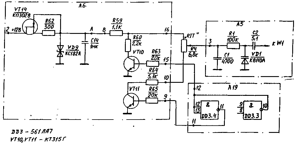
Encyclopedia of radio electronics and electrical engineering / Civil radio communications This article considers the problem of increasing the temperature stability of the operating frequency of the RA3AO transceiver by introducing into its composition a circuit for thermal compensation of the supply voltage of the varicap of the frequency detuning unit. Increasing the temperature stability of the operating frequency of the RA3AO transceiver with a change in ambient temperature and self-heating of the device during operation can be achieved by thermal compensation of the supply voltage of the varicap VD 1 of the frequency detuning unit of the GPA A5 (Fig. 1 [1]).
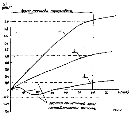
The principle of the proposed method of thermal compensation is that by changing the supply voltage of the varicap VD1, a frequency shift is achieved that is equal in magnitude, but opposite in sign, to the GPA frequency shift caused by temperature change [2,3]. Since the operating frequency of the RA3AO transceiver in the receive and transmit modes is determined, in addition to the GPA, by quartz oscillators in nodes L4, A7, L 19, by thermally compensating the total deviation of the operating frequency of all transceiver generators with one proposed device, it is possible to increase the stability of the transceiver operating frequency in the temperature range from -10°С to +50°С. When repeating the RA3AO transceiver, due to the variety of design features, materials used and the spread of parameters of components, the value and sign of the temperature shift of the operating frequency may have different values. In the thermal compensation scheme considered below, it is possible to select the sign and magnitude of the thermal compensation voltage. Experimental curves illustrating the frequency drift of the transceiver when the temperature inside the case changes with the operating time are shown in Fig. 2. Here, curve 1 shows the frequency drift of the transceiver without thermal compensation, curve 2 - the frequency drift of the transceiver with the thermal compensation scheme, but not adjusted enough to obtain the necessary frequency stability of the transceiver. Curve 3 illustrates the minimum drift of the transceiver's operating frequency for the optimally selected operating mode of the thermal compensation circuit.
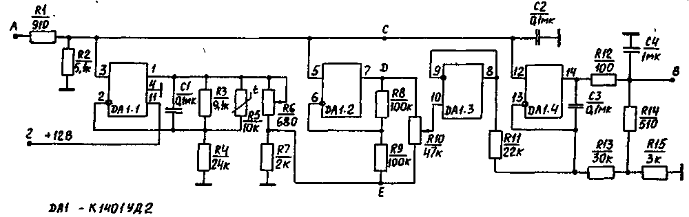
An analysis of curves 1-3 (Fig. 2) shows that with the help of a thermal compensation unit, it is possible to achieve a decrease in the frequency deviation of the transceiver associated with its self-heating, and reduce the frequency instability of the transceiver to a drift value at a steady temperature regime of the transceiver. The proposed thermal compensation scheme ensures the instability of the transceiver's operating frequency of no more than 200 Hz for several hours of its operation. It should be noted that the thermal compensation unit under consideration does not reduce the drift of the transceiver's operating frequency. The introduction of a thermal switch circuit requires little expense and slightly complicates the circuit of the RA3AO transceiver. It also does not lead to a change in the operation of the node by detuning the frequency of the transceiver. However, due to changes in the voltage on the VD1 varicap during thermal compensation, there is a slight change in the value of the frequency detuning range of the transceiver. The thermal compensation circuit can be used in any device that has parametric stabilization of the local oscillator frequency. The diagram of the thermal compensation unit is shown in Fig. 3, and its inclusion in the RA3AO transceiver is shown in Fig. 1. The thermal compensation unit is included in the gap (indicated by points A, B) of the power supply circuit of the VD1 varicap of the frequency detuning unit of the transceiver. The thermal commutation unit maintains the initial voltage at point B, equal to +8 V. It is made on a quad operational amplifier K 1401 UD 2L (B). As a temperature sensor, a thermistor (R5) is noted, through which a stable current flows, generated by the operational amplifier DA1.1. Linearization of the temperature dependence of the resistance of the resistor R5 in the temperature range from minus 10°C to plus 50°C is carried out using the resistor R3. The thermistor is mounted on the flea body of the GPA transceiver. A change in the temperature of the GPA unit leads to a change in the resistance value of the thermistor, which in turn leads to a voltage deviation at point E relative to the reference voltage at point C, equal to +7 V. by dU. Operational amplifier DA1.2 generates a voltage dU equal in magnitude and opposite in sign at point D.
By moving the slider of the variable resistor R10, it is possible to obtain at the output of the DA1.4 scale amplifier the necessary sign and value of the thermal compensation voltage relative to the output voltage of +8 V within ± 1 V when the thermistor temperature changes relative to room temperature by ± 30'C. The thermal compensation unit is mounted on a printed circuit board installed on the side wall of the GPA unit. The node uses resistors of the S2-ZZP or MLT type 0,125 W, SP5-1b, SP5-3B, capacitors of the KM type. The temperature resistor type ST4-16A or ST1-17 must have a reliable thermal contact with the body of the GPA unit. The K1401UD2A (B) chip can be replaced with two K140UD20 or four K140UD6 (K140UD608). Setting up the temperature compensation unit should be carried out in the following sequence. Preliminary adjustment of the thermal compensation unit is reduced to setting zero voltage between points C, D with a variable resistor R6. The voltage between points C, D must be controlled by a tester with a full deviation current of not more than 100 μA. Checking the correctness of the pre-setting of the node is reduced to monitoring the voltage at point B, which should be equal to + (8 ± 0,5) V at normal room temperature inside the transceiver. The final adjustment of the temperature compensation unit is carried out after an hour of warming up the transceiver. By adjusting the variable resistor R 10, the operating frequency of the transceiver is set, which was when it was turned on. After turning off and cooling down, the transceiver is turned on again and the stability of the operating frequency is checked, the drift of which should be similar to curve 3 in Fig. 2. Literature 1. Drozdov V.V. Amateur KB transceivers. - M.: Radio and communication, 1988.
Authors: V.Usov, V.Grinman; Publication: N. Bolshakov, rf.atnn.ru
A New Way to Control and Manipulate Optical Signals
05.05.2024 Primium Seneca keyboard
05.05.2024 The world's tallest astronomical observatory opened
04.05.2024
▪ Microbes in a squirrel wheel ▪ I waste household appliances - banned
▪ site section Digital technology. Article selection ▪ Hamlet article. Popular expression ▪ article Over what three seas did the Tver merchant Afanasy Nikitin travel? Detailed answer ▪ article Large-format printer. Job description
Home page | Library | Articles | Website map | Site Reviews
www.diagram.com.ua |

 Leave your comment on this article: