|
|


 Arabic
 Bengali
 Chinese
 English
 French
 German
 Hebrew
 Hindi
Hindi Italian
 Japanese
 Korean
 Malay
Malay Polish
 Portuguese
 Spanish
 Turkish
 Ukrainian
 Vietnamese
|
ENCYCLOPEDIA OF RADIO ELECTRONICS AND ELECTRICAL ENGINEERING Double-loop receiving antenna. Encyclopedia of radio electronics and electrical engineering
Encyclopedia of radio electronics and electrical engineering / VHF antennas The quality of radio reception in conditions of strong interference largely depends on the antenna used. In the article published below: the attention of readers is offered a description of the antenna, consisting of two frames and allowing you to achieve good reception in almost the entire broadcasting range. A loop antenna in the form of a winding located in a vertical plane is widely used for direction finding, broadcasting, radio communications and field strength measurements in the ultra-long to ultra-short wavelength range. However, noise-immune radio reception on a conventional loop antenna at any time of the day with strong radio interference is difficult due to the existence of the so-called "night error" [1]. This happens for the following reasons. First, interference coming at an angle to the horizon cannot be suppressed by a single loop antenna as effectively as interference coming in a horizontal direction. Secondly, noise suppression decreases as the vertical angle of its arrival increases. To stabilize the position of the plane of minimum reception and give the minimum of the directivity characteristic of zero value in the entire sector of vertical angles of arrival of the wave in radio direction finding, an antenna is used in the form of spaced frames connected in antiphase [1]. The spaced-frame antenna offered to the attention of readers is designed to be connected to a shielded radio receiver with a sensitivity of at least 50 μV and has the following technical characteristics: received frequency range - 0,15 ... 24 MHz; wave arrival azimuth - 0...360'; vertical angle of wave arrival - 0...90'; interference suppression in single and common mode - 0...30 dB; interference suppression in antiphase mode - not less than 30 dB; dimensions - 710x375x370 mm; weight - 3 kg. The scheme of the antenna with spaced frames is shown in fig. one.
It consists of two coaxial aperiodic single-turn frames WA1 and WA2, an operation mode switch SA1, a balun broadband transformer T1 and a shielded cable with an X1 connector for connecting to a radio receiver. In the T1 transformer, the transmission lines are located on a ferrite magnetic core. Unlike a traditional transformer with magnetic coupling between windings, it provides electromagnetic coupling between these lines. The paths of the currents from the input contacts X2, X1 of the transformer T2 to a common point at its output are equal. The transformer is selected according to the reference book [1]. At the same time, preference was given to its simplest version with a minimum value of asymmetry and an operating frequency range not less than that given in the technical characteristics of the antenna. Connecting a radio receiver with a balanced input to the contacts X2, X1 of the balanced output of the antenna allows you to exclude the transformer TXNUMX. All elements of the antenna are enclosed in a continuous electrical screen from the upper parts of the frames to the HZ connector. Through the XZ connector, the shielding circuit of the antenna is connected to the screen of the radio receiver. Screen gaps in the upper parts of the frames prevent complete electromagnetic shielding of the frames. The antenna can operate in one of three modes: single ("0"), in-phase ("C") and anti-phase ("P"). In the neutral position "0" switch SA1 enabled single mode. In this case, the WA1 frame works. When the SA1 switch is set to the "C" position, the frames are connected in phase and the antenna turns into a two-turn frame. The output signal level of such an antenna is equal to the sum of the signals from the outputs of the frames WA1, WA2. The common-mode mode is used when the antenna is exposed to a surface wave of interference, as well as with a weak signal and in the long-wave part of its operating range. In the "P" position of the SA1 switch, the anti-phase mode is activated. The level of the output signal of the antenna in this case is equal to the difference between the signals from the outputs of the frames WA1, WA2. The difference in the levels of the output signal of the antenna in the "C" and "P" modes decreases with increasing signal frequency and the spatial separation of the frames along their common axis. In the "P" mode, the change in the directivity of the antenna for a wave arriving at an angle to the horizon is eliminated. As a result, the noise suppression by the incoming spatial wave turns out to be equal to the noise suppression by the incoming surface wave. This mode is effective for strong signals in the shortwave part of the antenna operating range. Due to the low level of the antenna output signal, a highly sensitive shielded radio receiver with a switchable antenna is required to implement the spatial selectivity of the antenna. In the "P" mode, the direction of minimum reception is rotated around the vertical axis of the antenna by 90'. The directional characteristic of the antenna becomes four-lobe, which also increases the noise immunity of the reception. In the selected mode, the antenna is oriented in azimuth until the maximum signal-to-noise ratio is obtained at the output of the radio receiver.
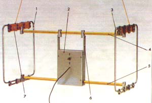
Antenna with spaced frames is shown in fig. 2. It consists of frames 1 and 3, located in parallel planes mirrored with respect to control panel 2, upper 4 and lower 5 traverses, two metallization bars 6, two insulators 7 and an output cable. The shape and strength of the frame is given by a supporting structure made of thin-walled steel pipe with a diameter of 8 mm. Each frame includes two such pipes having a C-shape. Their outer dimensions are 350x170 mm. A coaxial cable of brand RK75-2-11 is laid in the cavities of the pipes. The outer conductor of each cable has a 20 mm long break in the middle of the top of the frame. The length of the gap is equal to the gap between the tubes of the frame. The inner conductor has no breaks up to switch SA1 on the control panel. Traverses are made of duralumin tube with a diameter of 16 mm. The length of the upper traverse is 670 mm, the lower one consists of two parts 280 mm long. In the cavity of the pipes of the lower traverse, cables from the frames are laid, which are included in the duralumin box of the console with dimensions of 210x160x50 mm. Duralumin metallization busbars with dimensions of 112x22x4 mm fix the box and connect the upper traverse with the shielding elements of the antenna. Fiberglass insulators with dimensions of 240x30x4 mm together with elements 1-6 form a rigid supporting structure. For assembly, duralumin blocks and M4 and Mb mounting screws were used. The geometric symmetry, coaxiality and parallelism of the frames with the required tolerance of 0,2 "is ensured if the accuracy of the distances between the parts of the frames is not worse than 1 mm. The frames can be moved along the traverses in the process of assembling the antenna and adjusting the position of the frames. The permissible difference in the lengths of the cables of the frames is 10 mm. A P2T-1 toggle switch with a lock in the neutral position was used as a switch for operating modes on the control panel. The broadband transformer consists of a ferrite (M200NN2 brand) magnetic circuit in the form of three coaxially folded rings with dimensions K32x20x5 mm and two pieces of cable RK75-1-11. The cable segments are wound in the same direction, forming two windings containing eight turns each. The position of the turns is fixed by a polyethylene mandrel with a diameter of 20 and a height of 16 mm, introduced into the cavity of the magnetic circuit. On the cylindrical surface of the mandrel, 16 grooves are evenly spaced. Each winding occupies eight grooves of the mandrel, which corresponds to half of the magnetic circuit ring. The inner conductor of one of the segments is not used. Before assembling the transformer, a chamfer of 0,3 mm is removed from the outer edges of the magnetic circuit with sandpaper. To prevent electrical contact interference to radio reception, it is important to ensure the constancy of contacts between the shielding elements, as well as the isolation of the shielding elements in those places where contact should not be. The manufacture of the antenna is possible with a deviation from the above description. The volume reserve of the remote control box allows for the execution of the antenna in various versions. The value of the upper and lower operating frequencies of the transformer, as well as its design, depend on the size, number of rings, brand of the ferrite of the magnetic circuit and the number of turns of the windings. Permissible magnetic permeability of ferrite is not more than 200. With a smaller value, it is necessary to increase the number of rings of the magnetic circuit and the number of turns of the transformer windings. From rings smaller than K32x20x5 mm, it is possible to make a magnetic circuit in the form of a column, the height of which is limited by the dimensions of the console box and should not exceed 180 mm. A transformer with a columnar magnetic circuit 126 mm high, assembled from K20x12xbmm rings with a magnetic permeability of 150 ... 200, can contain two windings of three turns. The use of symmetrical lines of twisted winding wires will simplify the design of the transformer, but at the same time increase the asymmetry of the antenna circuit. We will replace the P2T-1 toggle switch with a switch for three positions and two directions. The volume of the remote control box allows placing a pre-amplifier with a power source and elements for tuning the frames into resonance in it. The noise figure of the preamplifier must be less than the noise figure of the radio receiver. In an extremely simplified antenna, the supporting structure can be made of wood, and a shielded wire with external insulation can be used for installation. The directivity characteristics of the antenna in the horizontal plane at frequencies of 8 ... 10 MHz, plotted in polar coordinates and on a single scale, are shown in Fig. 3. The measurements were carried out in the reception mode, which eliminates interference with operating radio equipment. In this case, a variable stepped (1 dB) attenuator was used with a maximum attenuation of 63 dB, a shielded radio receiver with a sensitivity of about 10 μV with a telegraph local oscillator and a switchable AGC, as well as an output indicator. When using a broadcasting receiver with a non-switchable AGC, the caliber measurement method proposed in [3] is used. To do this, an auxiliary ("calibrating") generator is connected to the radio receiver. If the generator frequency falls within the radio receiver bandwidth, and the generator output voltage level is 10 ... 100 times higher than the input signal level, then the dependence of the gain of the adjustable stages of the radio receiver on the input signal level decreases to the error of the output indicator. The perfection of the shielding of the radio receiver, and therefore its suitability for working with the antenna, is checked by the lack of reception after the built-in and external antennas are turned off. The screen can be made independently from foil or other electrically conductive material. It is located on the inner surface of the radio case. It should not form a closed loop around the built-in magnetic antenna. An AC voltmeter is suitable as an output indicator. The role of the reference signal
can emit any radio transmitter that has a stable level and the required field strength. During measurements, the telegraph local oscillator of the radio receiver should be turned on, and the AGC should be turned off. During the measurement, the level of the input signal of the radio receiver is maintained by a constant change in the attenuation of the attenuator and controlled by the output indicator. The level of the signal coming from the antenna is measured by the attenuation of the attenuator. Interference penetrating into the radio receiver through the power supply from the mains leads to measurement errors. As the ratio of the input signal level of the radio receiver to the level of interference penetrating the radio receiver from the network decreases, the error increases. The influence of mains interference is weakened by feeding the radio receiver from the mains through the noise protection unit or by using an independent power source. The frames are adjusted in the "P" mode according to the maximum suppression of the signal, in the direction of arrival of which the axis of minimum antenna reception is oriented. Literature 1. Kukes I. S., Starik M. E. Fundamentals of radio direction finding. - M.: Sov. Radio, 1964, p. 286,290.
Author: A.Kuzmenko, RV4LK, Ulyanovsk; Publication: N. Bolshakov, rf.atnn.ru
A New Way to Control and Manipulate Optical Signals
05.05.2024 Primium Seneca keyboard
05.05.2024 The world's tallest astronomical observatory opened
04.05.2024
▪ Device to quickly stop bleeding ▪ CMOS image sensor 2 megapixels 6 mm thick
▪ section of the site Lecture notes, cheat sheets. Selection of articles ▪ article Love will bloom, bloom and shrivel. Popular expression ▪ article What is a coronation stone? Detailed answer ▪ article Hygienic criteria and standards. Directory
Home page | Library | Articles | Website map | Site Reviews
www.diagram.com.ua |

 Leave your comment on this article: