Universal probe-indicator. Encyclopedia of radio electronics and electrical engineering

Encyclopedia of radio electronics and electrical engineering / Beginner radio amateur
 Comments on the article
When repairing and installing electrical wiring, it often becomes necessary to measure the mains voltage, determine the phase and neutral wires, and “ring out” the circuits for breaks or short circuits. An indicator - a phase indicator will not always be at hand, and the use of an avometer for these purposes is inconvenient due to the need to switch its operating modes.
The way out is to build the proposed device (see figure), consisting of an LED voltage scale, a control unit for the conductivity of electrical circuits ("continuity"), an AC voltage indicator and a phase wire indicator.
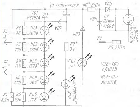
The LED scale is made on LEDs HL1-HL5 and resistors R2-R6, shunting the LEDs, and has five gradations of standard voltages. The operation of the scale is based on the ignition of a certain LED when the voltage across its shunt resistor is about 1.7 V. The VD3HL7 circuit serves to indicate the alternating voltage on the probe probes, as well as the reverse, compared to that indicated in the diagram, the polarity of the constant voltage on them.
The conductivity control unit consists of a storage capacitor C1 of a relatively large capacity, a VD1VD2 charging circuit and an R7HL6 indication circuit. When the probes are connected to a constant voltage source for a few seconds, the capacitor is charged through the diode VD2 from the voltage falling on the zener diode VD1. The probe is ready to "diagnose" the circuits. If the probes touch a working circuit, the capacitor discharge current will flow through it, resistor R1, LED HL6 and resistor R7. The LED will light up. As the capacitor discharges, the brightness of the LED will decrease. From one charge of the capacitor it is possible to make 8-12 checks.
The phase wire indicator is assembled according to the relaxation generator circuit. Touching the E1 sensor with your finger, connect any of the probes to the phase wire. The voltage rectified by the diodes VD4, VD5 charges the capacitor C2. When the voltage on it reaches a certain value, the HL8 neon lamp will flash. The capacitor is discharged through it, the process is repeated.
LEDs - indicated on the diagram or their foreign counterparts, for example, L-63IT It is desirable that they be close in parameters, and HL6 - with maximum light output at low current. Instead of the zener diode indicated on the diagram, it can be KS156A or D814B. Capacitor C1 - K50-35 or its foreign analogue (say, manufactured by Jamicon). Resistors R2-R9 - MLT of the corresponding power R1 - PEV, C5-37 with a power of at least 8 W (in extreme cases, you can install six series-connected MLT-2 resistors with a resistance of 1,3 kOhm).
The device is mounted in two cases made of dielectric material in the form of probes of the same size. Resistor R1 is placed in one probe, the rest of the device is in the other. The probes have pointed tips with a diameter of 3 and a length of 20 mm. The probes are interconnected by a flexible wire in double insulation, designed for a voltage of at least 380 V.
When adjusting the probe and working with it, precautions must be taken, since parts of the probe may be under high voltage!
If all parts are in good condition and mounted correctly, the probe can be used immediately. True, you may have to choose a resistor R7 in order to achieve a clear burning of the HL6 LED (when connected between the probes of a resistor with a resistance of 300 ... 400 Ohms). But its resistance should not be significantly reduced, since this will cause a rapid discharge of the storage capacitor. And in order to achieve clearly distinguishable flashes of a neon lamp, it is enough to choose a resistor R8.
Author: V.Sorokoumov, Sergiev Posad, Moscow region
 See other articles Section Beginner radio amateur.
Read and write useful comments on this article.
<< Back
 Latest news of science and technology, new electronics:
Machine for thinning flowers in gardens
02.05.2024
In modern agriculture, technological progress is developing aimed at increasing the efficiency of plant care processes. The innovative Florix flower thinning machine was presented in Italy, designed to optimize the harvesting stage. This tool is equipped with mobile arms, allowing it to be easily adapted to the needs of the garden. The operator can adjust the speed of the thin wires by controlling them from the tractor cab using a joystick. This approach significantly increases the efficiency of the flower thinning process, providing the possibility of individual adjustment to the specific conditions of the garden, as well as the variety and type of fruit grown in it. After testing the Florix machine for two years on various types of fruit, the results were very encouraging. Farmers such as Filiberto Montanari, who has used a Florix machine for several years, have reported a significant reduction in the time and labor required to thin flowers.
... >>
Advanced Infrared Microscope
02.05.2024
Microscopes play an important role in scientific research, allowing scientists to delve into structures and processes invisible to the eye. However, various microscopy methods have their limitations, and among them was the limitation of resolution when using the infrared range. But the latest achievements of Japanese researchers from the University of Tokyo open up new prospects for studying the microworld. Scientists from the University of Tokyo have unveiled a new microscope that will revolutionize the capabilities of infrared microscopy. This advanced instrument allows you to see the internal structures of living bacteria with amazing clarity on the nanometer scale. Typically, mid-infrared microscopes are limited by low resolution, but the latest development from Japanese researchers overcomes these limitations. According to scientists, the developed microscope allows creating images with a resolution of up to 120 nanometers, which is 30 times higher than the resolution of traditional microscopes. ... >>
Air trap for insects
01.05.2024
Agriculture is one of the key sectors of the economy, and pest control is an integral part of this process. A team of scientists from the Indian Council of Agricultural Research-Central Potato Research Institute (ICAR-CPRI), Shimla, has come up with an innovative solution to this problem - a wind-powered insect air trap. This device addresses the shortcomings of traditional pest control methods by providing real-time insect population data. The trap is powered entirely by wind energy, making it an environmentally friendly solution that requires no power. Its unique design allows monitoring of both harmful and beneficial insects, providing a complete overview of the population in any agricultural area. “By assessing target pests at the right time, we can take necessary measures to control both pests and diseases,” says Kapil ... >>
| Random news from the Archive Hydrogen crossover Audi H-Tron Quattro
12.01.2016
Audi at the North American International Auto Show in Detroit for the first time demonstrated the concept crossover H-Tron Quattro, powered by hydrogen.
The power plant of the car combines a block of hydrogen fuel cells and a battery. An electric motor with a power of 90 kW (121 horsepower) is installed on the front axle, and a power of 140 kW (188 horsepower) is installed on the rear axle.
Audi claims that the crossover can accelerate from 0 to 100 km/h in less than 7 seconds. At one gas station, the car can cover a distance of up to 600 km; replenishment of hydrogen reserves takes approximately four minutes.
The H-Tron Quattro also showcases advanced self-driving and automatic parking technologies. Audi's autopilot system will debut on the next-generation Audi A8 executive sedan due in 2017. The technologies of this system can control the car during parking or driving in heavy traffic with frequent stops and starting on the highway at speeds up to 60 km/h.
In addition, the concept uses a new generation virtual dashboard, which we talked about the other day. It features large Active Matrix Organic Light Emitting Diode (AMOLED) displays with haptic feedback. Mobile devices such as smartphones and smart watches can be connected wirelessly.
|
Other interesting news:
▪ Plant Census of China
▪ Aqua Computer Kryographics Next full coverage water blocks
▪ The cage backs up
▪ Buildings of the future
▪ Broadband Internet is an inalienable human right
News feed of science and technology, new electronics
 Interesting materials of the Free Technical Library:
▪ section of the site Signal limiters, compressors. Article selection
▪ article Fun puzzles
▪ article How much of the world's wine production improves with age? Detailed answer
▪ article Carrier. Standard instruction on labor protection
▪ article A simple amplifier for a free-energy receiver. Encyclopedia of radio electronics and electrical engineering
▪ article AC voltage stabilizer. Encyclopedia of radio electronics and electrical engineering
Leave your comment on this article:
 All languages of this page
Home page | Library | Articles | Website map | Site Reviews

www.diagram.com.ua
2000-2024


 Arabic
 Bengali
 Chinese
 English
 French
 German
 Hebrew
 Hindi
Hindi Italian
 Japanese
 Korean
 Malay
Malay Polish
 Portuguese
 Spanish
 Turkish
 Ukrainian
 Vietnamese