|
|


 Arabic
 Bengali
 Chinese
 English
 French
 German
 Hebrew
 Hindi
Hindi Italian
 Japanese
 Korean
 Malay
Malay Polish
 Portuguese
 Spanish
 Turkish
 Ukrainian
 Vietnamese
|
ENCYCLOPEDIA OF RADIO ELECTRONICS AND ELECTRICAL ENGINEERING Stand for measuring the throughput of carburetor jets. Encyclopedia of radio electronics and electrical engineering
Encyclopedia of radio electronics and electrical engineering / Automobile. Electronic devices Despite the fact that the production of carburetted cars has been reduced to a minimum, millions of such cars are still in operation. To maintain their performance at the proper level, it is often necessary to repair carburetors. One of the important indicators of the correct operation of the carburetor is the throughput of the jets. It is possible to measure this parameter only with the help of a special stand. When the carburetor is operating in general, but on domestic fuel, all the more so, the calibrated part of the jet is resinified rather quickly. An almost invisible film of resin can significantly reduce the performance of the jet. In many cases, motorists, trying to independently adjust the operation of the engine, replace the factory jets with repair ones from kits of dubious origin. As measurements on a special stand show, the deviation from the norm in such cases reached tens of percent. It is not difficult to understand the consequences of this. Measurement of the throughput of jets is usually carried out on specialized stands. Hydrodynamic stand NIIAT-528-A industrial production is very complicated, expensive and inconvenient to use. Therefore, I decided to make an amateur version of such a stand with a simpler hydraulic circuit and automatic control of the water supply to the jet under test. The measurement algorithm is simple. Under the pressure of a water column 1000 ± 2 mm high, the liquid flows through the jet into a graduated beaker. Automation provides a stable flow time - 60 s. Thus, the throughput of the jet is determined in milliliters per minute.
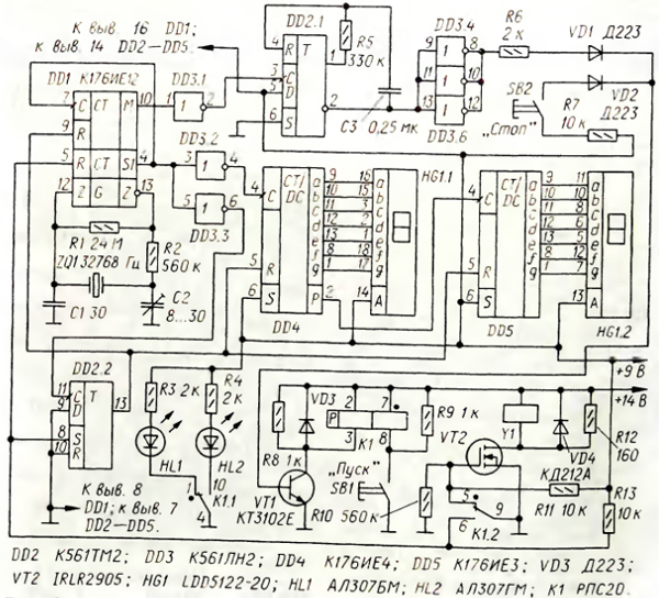
The hydraulic part of the stand is schematically shown in fig. 1 It consists of a tank into which a pressure pipe is hermetically welded (or soldered). From below, it ends with a solenoid valve, the test nozzle is screwed into its outlet. I used a Belarusian-made gas valve from gas-balloon automotive equipment, bought at an auto parts store. To reduce hydraulic resistance, I drilled out the valve inlet pipe to a diameter of 2,8 mm and removed the felt filter. In the lower part of the tank, a fitting is welded into its side wall, which is connected to the inlet pipe of the water pump (the pump was used from the interior heater of the Gazelle minibus). Through the upper pipe, the pump drives water into the pressure pipe. Excess water flows from the upper end of the pipe into the tank. Thus, the system maintains a constant pressure of water above the jet. Since the performance of the pump is excessive, in order to avoid splashing of the flowing water, a valve is introduced into the outlet pipe of the pump, which limits the flow of water into the pressure pipe. The tank and pressure pipe are made of stainless steel, but aluminum alloy, brass, and even plastic are also suitable. The dimensions and shape of the stand elements are not critical. Only the height of the pressure pipe should be accurate (its diameter in my version of the stand is about 50 mm).
The scheme of the electronic control unit for the water supply to the jet is shown in fig. 2 The counter DD1 has a timer designed for a shutter speed of 60 s. Since the K176IE12 counter is designed to work in an electronic clock, the minute signal appears at the output M of the counter after 59 s. To obtain a sixty-second exposure, a separate zeroing of the timer counters was used using the synchronization trigger DD2.2. On the counters DD4, DD5 and the digital indicator HG1, a unit for counting the measurement time is assembled, operating in the addition mode. Single vibrator on the elements DD2.1, R5, C3 controls the operation of the executive relay K1. It is a remote switch with two windings and two stable states, switched by current pulses. For reliable operation of the relay, the pulse duration of a single vibrator is approximately 50 ms. Elements DD3.4-DD3.6 invert and amplify the current signal of the single vibrator to the level necessary for reliable opening of the transistor VT1 and relay K1 operation. Diodes VD1, VD2 form a logical OR element. The relay, having worked, switches its contacts K1.2. As a result, a powerful transistor VT2 opens and valve Y1 is activated, which opens the water supply to the jet. The process of measuring its throughput consists of several stages. The tested jet is screwed into the lower branch pipe of the valve and the pump is turned on; the pressure pipe of the stand is filled with water. A measuring cup is placed under the jet. The relay node is in the "Stop" position. Transistor VT2 is closed, since its gate is connected to a common wire by contacts K1.2. Therefore valve Y1 is closed. Through the resistor R13, a voltage is supplied to the input R of the second counter of the DD1 microcircuit, blocking its operation, and the minute counter is blocked by the voltage from the output of the trigger DD2.2. This voltage also blocked the operation of the counters DD4, DD5 of the exposure time indication unit. The LED HL1 "Stop" red glow is on. Next, click on the "Start" button. Contacts K1 1 and K1.2 of the relay switch to the second stable state. Transistor VT2 opens, valve Y1 operates, and water begins to flow through the jet. At the same time, the second counter of the DD1 chip starts to work, and after one second, the DD2.2 trigger will switch to the zero state, which will lead to the unlocking of the minute counter of the DD1 chip and counters DD4, DD5. HG1 indicator starts timing. Contacts K1.1 of the relay turn on the "green" LED HL2 "Start" and turn off HL1. After 60 s, a signal will appear at the output M of the DD1 chip, which will start the one-shot on the trigger DD2.1. As a result, transistor VT50 will open for 1 ms and switch relay K1 to its original state. This will close the transistor VT2 and shut off the water supply to the jet. The capacity of the jet is determined by the volume of water in the measuring cup. By pressing the SB2 "Stop" button, you can switch the relay and stop the measurement process before the exposure time expires. The electronic unit is assembled on the technological board; the installation is made with pieces of insulated flexible wire. The unit is installed in a metal box, on the front panel of which are mounted controls, a digital indicator and LEDs. Remote switch - RPS20, version RS4.521.753 The power supply unit - transformer has no circuit features. It contains two voltage sources - stabilized at 9 V and unstabilized at 14 V. Author: I. Osipov, Kursk; Publication: radioradar.net
Artificial leather for touch emulation
15.04.2024 Petgugu Global cat litter
15.04.2024 The attractiveness of caring men
14.04.2024
▪ Ultra-precise X-ray system for airports ▪ Trees will help find the bodies of people missing in the forest
▪ site section Chargers, accumulators, batteries. Article selection ▪ article Symbols for SMD transistors. Directory ▪ Article Who, according to Albert Einstein, makes great discoveries? Detailed answer ▪ the article of Ziziphorus is thin. Legends, cultivation, methods of application ▪ article Watch shop in a hat. Focus Secret
Home page | Library | Articles | Website map | Site Reviews
www.diagram.com.ua |


 Leave your comment on this article: