|
|


 Arabic
 Bengali
 Chinese
 English
 French
 German
 Hebrew
 Hindi
Hindi Italian
 Japanese
 Korean
 Malay
Malay Polish
 Portuguese
 Spanish
 Turkish
 Ukrainian
 Vietnamese
|
ENCYCLOPEDIA OF RADIO ELECTRONICS AND ELECTRICAL ENGINEERING A simple voltage regulator. Encyclopedia of radio electronics and electrical engineering
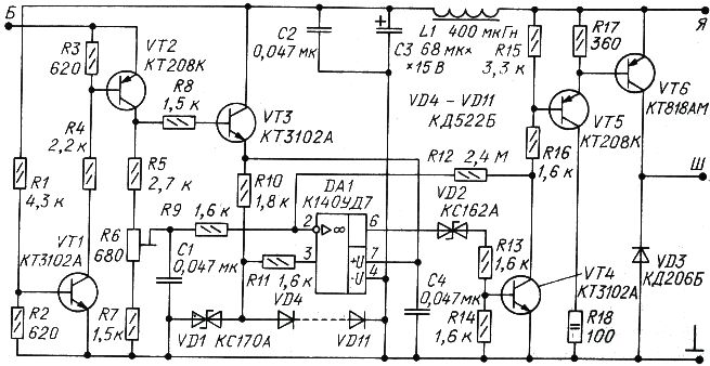
Encyclopedia of radio electronics and electrical engineering / Automobile. Electronic devices Most of the described amateur voltage regulators for a car, as well as industrial regulators that are equipped with mass-produced cars, are designed to maintain an unchanging stable voltage at the generator terminals. With an increase in load (turning on headlights, a fan and other consumers), the voltage drop on the wires increases, and the voltage of the on-board network decreases accordingly, and the battery charging current also decreases. To stabilize the voltage at the battery terminals, the regulator input is connected directly to the battery. As you know [L], for normal recharging of the battery, the voltage at its terminals should be increased with decreasing temperature. Therefore, the independence of the voltage stabilized by the regulator from temperature should be considered a big drawback. Even if the regulator is able to adjust the voltage depending on the temperature of the engine compartment, this is not enough. Tuned for optimum performance in the summer, the regulator puts the battery in a tough spot in the winter, when the air under the hood warms up quickly and the battery itself after only a few hours of driving. As a result, the battery remains undercharged, and in the cold season it has to be recharged. If the regulator is set up for optimal operation in cold weather, in the summer it will recharge the battery, and you will have to periodically add distilled water to it. The best solution is to control the temperature of the battery itself and the voltage at its terminals with a regulator. Just such a controller is described in [L], but it is rather complicated, contains an electromagnetic relay and scarce stabistors in the temperature sensor. The voltage regulator described here does not contain a relay; low-power silicon diodes are used as a sensor. In addition, it is significantly simpler in design. According to [L], the required absolute voltage temperature coefficient (TKV), which the regulator must provide, is -40,5 mV / ° C, or in relative units -0,298% / ° C. Approximately the same relative temperature coefficient of voltage has low-power silicon diodes with a forward current of several milliamps, as well as stabistors, which are several diodes connected in series. The absolute TKN of one diode is about -2 mV / ° С, which, with a voltage drop of 650 mV across it, gives a relative value of -2 / 650 \u0,307d -1% / ° С. Note that the relative value of the TKN of a circuit of several diodes or stabistors does not depend on their number. The controller circuit is shown in Fig.XNUMX.
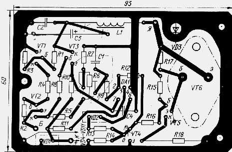
Output B of the regulator is connected with a separate wire to the positive terminal of the battery, outputs I and W - to the output of the generator rectifier bridge and to its excitation winding, respectively. The common wire of the regulator is connected to the car body at the place where the regulator is installed. A chain of eight VD4-VD 11 diodes is attached to the battery case and has thermal contact with it. This circuit serves as a temperature-dependent source of reference voltage with the necessary TKN. When the ignition of the car is turned off, there is no voltage at the terminal I, the transistors VT1-VT3 are closed, the supply voltage is not supplied to the operational amplifier DA1, the transistors VT4-VT6 are also closed, only the initial collector current of the transistors VT1 and VT2 is consumed from the battery, which is immeasurably less than the battery self-discharge current . When the ignition is turned on, the transistors VT1-VT3 open, through the transistor VT3, the supply voltage is supplied to the op-amp DA1. The voltage from the positive terminal of the battery through the transistor VT2 is connected to the divider R5R6R7, and from the engine of the resistor R6 - to the inverting input of the op-amp DA1. Voltage is applied to the non-inverting input of the op-amp from a circuit of diodes VD4-VD11. While the engine is off, the voltage taken from the resistor R6 engine is less than the voltage drop across the VD4-VD11 diodes, the voltage at the output of the op-amp is close to the battery voltage and the transistors VT4-VT6 are open, current flows through the excitation winding of the generator. After starting the engine, the generator begins to generate current, the battery voltage increases, the operational amplifier DA1 switches, transistors VT4-VT6 close, current. generated by the generator decreases, as a result of which the op-amp is switched again and the current increases through the excitation winding of the generator. The opening and closing of transistors VT4-VT6 occurs at a frequency of several tens or hundreds of hertz, maintaining the required voltage at the battery terminals. Positive feedback through the resistor R12 provides the op-amp hysteresis and turns the op-amp into a Schmitt trigger. The zener diode VD2 matches the output voltage of the op-amp with the switching threshold of the transistor VT4. Of particular note is the role of the zener diode VD1, which is closed in the normal mode of operation of the regulator. If it were not there, then if the wires leading to the VD4-VD11 temperature sensor were broken, the current would flow continuously through the excitation winding of the generator, the voltage of the on-board network would increase greatly, which is dangerous both for the battery and for other consumers of electricity. The zener diode VD1, when the temperature sensor is turned off, opens and starts working as a source of exemplary voltage. The voltage in the on-board network, although it increases, is not as significant as in its absence. Design All elements of the regulator, except for the diodes VD4-VD11, are placed on a printed circuit board with dimensions of 93x60 mm made of fiberglass 1,5 mm thick - The drawing of the board is shown in Fig. 2.
The VT6 transistor is mounted on a board without a heat sink on two brass bushings, the base and emitter leads are soldered directly to the board. The board is designed for installation in the housing of the electromechanical relay-regulator RR-24 on three threaded brass posts. The outputs are the corresponding outputs on the case. The temperature sensor consists of three plates folded into a package with dimensions of 80x30x2 mm, one brass and two fiberglass. In the middle fiberglass plate, approximately in its middle, a window with dimensions of 50x8 mm is cut. Eight diodes connected in series are placed in this space. The conclusions from the MGTF-0,14 wire are placed in a PVC tube laid in a narrow groove sawn in the middle plate. The entire structure is glued together with epoxy putty, and the inner cavity of the middle plate is also filled with it. The brass plate must be tinned before gluing, all parts of the sensor must be thoroughly degreased. The sensor leads are soldered directly to the corresponding points on the PCB. For reliability, it is desirable to additionally attach the conclusions to the regulator body with a small clamp. With a brass plate, the sensor is slightly pressed into the heated mastic for filling the battery. If it does not have a mastic fill, the brass plate should be pressed against a flat section of the side surface of the battery case with a rubber ring cut from the wheel chamber. Conclusion B of the regulator is more convenient, connect not to the positive terminal of the battery, but to the positive current clamp of the starter. Details In the controller, instead of KT3102A (VT1, VT3, VT4) and KT208K (VT2), almost any low-power silicon transistors of the corresponding structure can be used. Transistor VT5 must allow a collector current of at least 150 mA; here you can use transistors from the KT208, KT209, KT313, KT3108, KT814, KT816 series with any letter index. Preference should be given to transistors in a metal case. Zener diode VD2 - any for a voltage of 3,3 ... 7 V. The VD3 diode can be any for a direct current of at least 3 A. It is convenient to mount the diodes of the KD206 series on the board, since the anode is placed on their case. Capacitors C1, C2, C4 - KM5 or KM6, C3 - K53-1 or K53-4. The use of capacitors of the K50 or K52 series is undesirable. Throttle L1 - DM-0,1; fixed resistors - MT or MLT, tuning R6 - SPZ-19a. adjust the device follows in a certain order. First, an adjustable DC voltage source up to 16,5 V is connected to the output B of the regulator and to the case and the current consumed from it is measured. The pointer of a 100 µA microammeter should not deviate noticeably. Next, a 120 Ohm resistor with a power of 2 W is connected between the Ш terminal and the common wire with a voltmeter connected in parallel (or a low-power incandescent lamp for a voltage of 18 ... 24 V). The output I is connected to the same source, setting its voltage equal to 13,6 V, and the resistor R6 sets such a switching threshold at which the output voltage at the output Ш is close to zero when the source voltage increases above 13,6 V and is close to the supply voltage at voltage drops below this value. Then the VD4-VD11 diode circuit is turned off and the VD1 zener diode is selected, achieving a similar switching of the regulator at a power supply voltage of 16 ... 16,5 V. When selecting, if necessary, you can turn on one or two low-power silicon diodes in direct direction. More precise adjustment is carried out on the car. Having fully charged the battery, a voltmeter (preferably digital) measures the voltage at its terminals without load. The engine is started without a starter and resistor R1 sets the measured voltage value at the battery terminals. If there is an ammeter on the car, the criterion for the correct adjustment of the device can be the value of the charging current 6 ... 5 minutes after starting the engine at an average crankshaft speed and a charged battery. The current must be within 10 ... 2 A, regardless of the power of the included load. The regulator described above with the traditional temperature-compensated D818E zener diode instead of the VD1 and VD4-VD11 diodes worked for several years on a GAZ-24 car. In the summer, it was necessary to add water to the battery, in spring and autumn - to recharge it. After installing the VD4-VD11 sensor, the need for these operations has disappeared. Together with the use of a thyristor-transistor electronic ignition unit with an extended spark, which provides a quick start of the engine in a wide variety of operating conditions, the described voltage regulator made it possible to increase the battery life to nine years. Literature
Author: S. Biryukov; Publication: radioradar.net
Air trap for insects
01.05.2024 The threat of space debris to the Earth's magnetic field
01.05.2024 Solidification of bulk substances
30.04.2024
▪ NLSF595 Tricolor LED Drivers ▪ Universal Power Controllers for TWS Wireless Headphones
▪ section of the site Children's scientific laboratory. Article selection ▪ article You must cultivate your garden. Popular expression ▪ article What is Jazz? Detailed answer ▪ article User of personal electronic computers PC. Standard instruction on labor protection ▪ article Mastic varnish for oil paintings. Simple recipes and tips ▪ article Kabardian proverbs and sayings. Large selection
Comments on the article: Peter I would like to know the secret - what kind of diodes VD4-VD11?
Home page | Library | Articles | Website map | Site Reviews
www.diagram.com.ua |

 Leave your comment on this article: