|
|


 Arabic
 Bengali
 Chinese
 English
 French
 German
 Hebrew
 Hindi
Hindi Italian
 Japanese
 Korean
 Malay
Malay Polish
 Portuguese
 Spanish
 Turkish
 Ukrainian
 Vietnamese
|
ENCYCLOPEDIA OF RADIO ELECTRONICS AND ELECTRICAL ENGINEERING Digifant engine management system. Working principle and functional parameters
Encyclopedia of radio electronics and electrical engineering / Automobile. Electronic fuel injection Volkswagen's Digifant integrated engine management system consists of two subsystems: fuel injection control and ignition timing control. The operation of all subsystems is controlled by an electronic controller, which is a specialized micro-computer.
Fuel injection control subsystem
The subsystem is responsible for the preparation of the fuel mixture and its supply to the engine. In this case, to each cylinder, the fuel mixture is supplied by a separate nozzle. The subsystem works as follows: Electric fuel pump under pressure of 2,5 kg/cm2 supplies fuel from the gas tank through the fuel filter to the fuel path and further to the injectors. At the end of the fuel path, a fuel pressure regulator is installed in the system, which maintains a constant injection pressure and drains excess fuel back into the fuel tank, thereby ensuring fuel circulation in the system and eliminating the formation of fuel vapors in it. Depending on the information received from the sensors installed on the engine, the electric controller controls the injectors, thus regulating the amount of the fuel mixture supplied to the cylinders. At the same time, the volume and temperature of the intake air, the speed and angle of the crankshaft position, the engine load and the temperature of its coolant are taken into account. In addition, when a lambda probe is installed, the electric controller also takes into account its information, thus optimally maintaining the content of harmful impurities in the exhaust gases. The main parameter that determines the dosage of fuel is the volume of intake air. The air flow entering through the filter deflects the pressure damper at a certain angle, which is connected to a potentiometric sensor for the deflection angle of this damper. The signal from the air damper position sensor enters the electric controller, and it determines how much fuel is needed at the moment and issues the appropriate control signals for opening the injectors for the required time. Regardless of the position of the intake valves, fuel is injected twice for each revolution of the crankshaft. If the intake valve is closed, fuel remains in the intake manifold until the next intake valve opening for that cylinder. Enrichment of the fuel mixture in starting modes can be carried out by supplying additional fuel by the main injectors, such as in "RV" engines, or by additional injectors controlled by an electronic controller, as in the "2E" engine. When the specified engine speed is exceeded and at forced idle, the electric controller stops the control of the injectors, thus stopping the supply of fuel to the engine cylinders. Dosing of air supply during start-up, warm-up and idling is carried out by the idle speed stabilization valve.
Functional parameters Fuel pump. Electric submersible roller fuel pump. It is installed in the fuel tank in one unit with the fuel level sensor. Brand and catalog number: BOSCH 0 580 453 012. Fuel supply pressure - 3 kg/cm2. Productivity at a supply voltage on conclusions: - 9v: 275 cm3/30sec. - 10v: 350 cm3/30sec. - 11v: 425 cm3/30sec. - 12v: 500 cm3/30sec. in all parameters + -10 cm3 / 30 sec.
Fuel pressure control. Diaphragm type fuel pressure regulator. It is installed on the fuel path and serves to ensure constant fuel pressure in the system. Idling control pressure: - with a vacuum tube connected: 2,5 kg/cm2; - with the vacuum tube disconnected: 3,0 kg/cm2. Calibration pressure: +-0,2 kg/cm2. Residual pressure in the system after 10 min. after turning off the fuel pump, not less than 2kg/cm2.
Air flow meter. Air flow meter with pressure disc to measure the amount of air entering the engine. Potentiometric. Mounted on the axis of the pressure disc, with a resistive type intake air temperature sensor built into the housing and a negative temperature coefficient (with increasing temperature, the resistance decreases). Brand: Bosch. Catalog numbers: factory setting - 0 280 200 241; spare part - 0 289 200 242. Resistance of the potentiometric sensor when measured between the terminals of the air flow meter connector: - "3" and "4": 500-1000 ohm; - "2" and "3": continuously variable depending on the position of the pressure plate. The resistance of the intake air temperature sensor when measured between terminals "1" and "4" of the air flow meter connector and at air temperature: - 0С: 5,5 + -0,7 kOhm; - 20C: 2,5 + -0,5 kOhm; - 30C: 1,8 + -0,2 kOhm; - 50C: 0,8 + -0,1 kOhm; - 80C: 0,35 + -0,05 kOhm; - 100C: 0,2 + -0,025 kOhm.
Coolant temperature sensor. The coolant temperature sensor is the same type as the intake air temperature sensor and has the same specifications.
Throttle Position Sensors Option 1.
Installed idle sensor and full load sensor. Both sensors are position type. Mounted on the throttle shaft. Serve to determine the operating mode of the engine. The resistance of the idle speed sensor with a gap of 0,2-0,6 mm. between the throttle control lever and the idle stop - 0,5 Ohm. The resistance of the full load sensor at an angle of 10+-2 degrees between the throttle valve and the full load stop is infinity.
Option 2.
Throttle position sensor potentiometric type. Mounted on the throttle shaft. Voltage when measured between terminals "2" and "3" of the sensor connector: - with the throttle valve at the idle stop or full load: 0-0,5v. - at an intermediate throttle position: 4,5-5,0v.
Idle stabilization valve. The idle air stabilization valve is electromagnetic, rotary type. It is installed in the air path, parallel to the throttle body and ensures constant engine speed at idle by changing the flow area of the air channel.
Exhaust oxygen sensor (lambda probe). The sensor provides information to the controller about the oxygen content in the exhaust gases. Mounted on the engine exhaust manifold. Supply voltage - 12V. Output current - 0,5-3,0A. Ignition Timing Control Subsystem The main elements of the ignition timing control subsystem are: an electronic controller, a switch, an engine speed sensor (Hall sensor) built into the ignition distributor, a vacuum sensor built into the controller, a knock sensor, a coil and spark plugs. The knock sensor provides control over the engine load and is the main one for regulating the ignition timing. The ignition advance angle is calculated by the electronic controller in direct proportion to the readings of the sensors, and it also controls the ignition. Functional parameters Distributor. Ignition distributor with axial outputs, with built-in Hall sensor. It is used to distribute the ignition among the cylinders, to determine the number of engine revolutions and the moment of sparking. Catalog number: BOSCH 0 237 520 010. The initial ignition timing to TDC with the coolant temperature sensor connector disconnected - 6 degrees + -18 seconds. The output voltage of the Hall sensor when measured between terminals "4" and "6" of the switch connector is 0-2V. Hall sensor rotor resistance - 0,6-1,4 Ohm.
Switch. Part number: BOSCH 0 227 100 142
Ignition coil. Ignition coil with gray or green markings. The resistance of the primary winding is 0,6-0,8 ohms. The resistance of the secondary winding is 6,9-8,5 kOhm.
Elements of radio interference suppression. The resistance of noise suppression resistors is 0,6-1,4 kOhm. The resistance of the tips of the spark plugs is 4,0-6,0 kOhm. Structural diagram of the engine management system - "DIGIFANT" 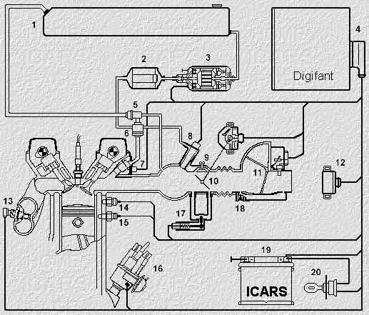 1. Fuel tank 2. Fuel filter 3. Fuel pump 4. Electronic control unit 5. Fuel pressure regulator 6. Fuel storage 7. Injector 8. Starting nozzle 9. Adjustment screw X.X. 10. Throttle valve 11. Air flow meter 12. Control relay 13. Lambda probe 14. Knock sensor 15. Coolant temperature sensor 16. Ignition distributor 17. Stabilization valve Kh.Kh. 18. CO adjustment screw 19. Battery 20. Egnition lock Publication: cxem.net
See other articles Section Automobile. Electronic fuel injection
Machine for thinning flowers in gardens
02.05.2024 Advanced Infrared Microscope
02.05.2024 Air trap for insects
01.05.2024
▪ site section Mobile communications ▪ Radioamator Notebook magazines (annual archives) ▪ book Measuring devices for radio amateurs. Dudich I.I., 1967 ▪ article What is an eye cataract? Detailed answer ▪ reference book Foreign microcircuits and transistors. G-series
Home page | Library | Articles | Website map | Site Reviews
www.diagram.com.ua |

 Leave your comment on this article: