|
|


 Arabic
 Bengali
 Chinese
 English
 French
 German
 Hebrew
 Hindi
Hindi Italian
 Japanese
 Korean
 Malay
Malay Polish
 Portuguese
 Spanish
 Turkish
 Ukrainian
 Vietnamese
|
ENCYCLOPEDIA OF RADIO ELECTRONICS AND ELECTRICAL ENGINEERING Transistor UMZCH. Encyclopedia of radio electronics and electrical engineering
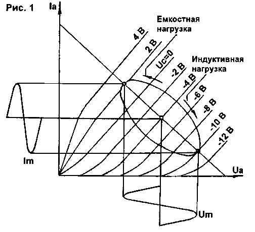
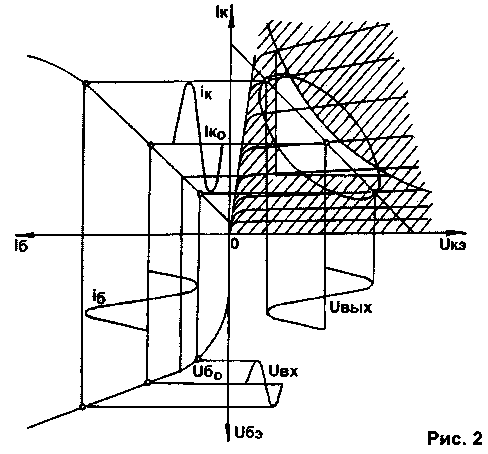
Encyclopedia of radio electronics and electrical engineering / Transistor power amplifiers Usually, considering the operation of the UMZCH, it is assumed that its load is purely active. However, a loudspeaker, and even with smoothing filters, is a complex complex load. When operating on a complex load, the resulting phase shift between voltage and current at the output of the amplifier leads to the fact that with sinusoidal input signals, the load straight line turns into an ellipse. The position of the operating point (load curve) for the reactive load on the output characteristics of the triode and transistor when amplifying a harmonic signal is shown in fig. 1 and 2, respectively.
As can be seen from fig. 1, the output characteristics of a triode are almost ideal for a complex load such as AC. A favorable range of harmonics (not higher than the fifth) and high linearity largely determine the "softness" of the sound of tube amplifiers. At the same time, a single-ended transistor amplifier is completely unsuitable for working with a loudspeaker, because. the load line enters, on the one hand, into the region of limitation on the allowable power dissipation on the collector (shaded region, above the hyperbola), on the other hand, into nonlinear regions at small Uke. The transverse dimension of the ellipse of the load curve depends on the inductive component of the load, and the longitudinal dimension depends on the active component. When amplifying impulse signals, for example, of the "meander" type, the load line is a parallelogram [1], which further aggravates the situation. The amplitude of the voltage jump at the moment of switching (due to self-induction EMF) depends on the ratio of the signal time constant To to the load time constant T=L/R. At t>To, in order to eliminate the possibility of breakdown of the output transistors (for example, in class D amplifiers with PWM), reverse-connected diodes are installed in parallel with the output transistors. On fig. 3 shows the load characteristics of the push-pull output stage of the transistor UMZCH on a family of output current-voltage characteristics with a purely resistive load (direct) and with a complex load (ellipse) within the safe operation region (OBR) of DC transistors.
In this case, the maximum power dissipation for each transistor of the output stage arm increases in proportion to the phase shift <p of the load vector (Fig. 4). The typical value of the phase shift is usually in the range of 25...60°, but in rare cases it reaches 80°.
Since the impedance of the acoustic system (AS) is inductive, the vector of which Z1=RL+ZL has a direction opposite to the direction of the capacitive load vector (Fig. 4), it is possible to select an RC circuit (Buchet compensator) with an impedance Z2=R+Zc, compensating inductive component of the load. As a result, the speaker impedance becomes purely active and does not depend on frequency. Compensation conditions [1]:
where RL is the equivalent of the active resistance of the loudspeaker (4...10 Ohm); C \u0,1d XNUMX uF. The impulsive nature of a real sound signal and the complex nature of the loudspeaker impedance lead to the fact that the peak value of the output current is 5...8 times higher than the maximum amplitude value Im, corresponding to operation on an active load. So, for example, with an output power of 60 W and a load resistance of 4 ohms, the peak current value at the output can be 5,5 A with a resistive load and 33 A with a complex one. This shows how important it is to choose the right compensating RC chain and have a sufficient margin of UMZCH power. On fig. 5 shows a diagram of the operation of terminal transistors in the AB mode, where Uo1, Uo2 are their initial bias; lo1, lo2 - quiescent current.
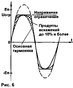
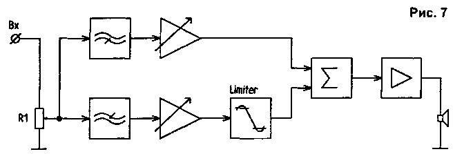
With absolute symmetry of the cascade, the total characteristic is a straight line, otherwise there is a bend in one direction or another [З]. The sound of tube equipment is often characterized by such epithets as "velvet", "soft", "warm", natural, etc. What caused it? First of all, the fact that for lamps the level of distortion increases slowly with increasing signal, reaching values of several percent. Such dependence is called "monotonic distortion". Moreover, harmonics above the third are practically absent. It is not for nothing that Hi-Fi class amplifiers (High Fidelity - "high fidelity") are being replaced mainly by tube amplifiers of the Hi End class (High End - "high total", "highest") with a non-linear distortion factor of up to 1%. In transistor amplifiers, distortions are low only in the working area and increase sharply when crossing its boundaries. A characteristic feature of the vast majority of transistor amplifiers is a clear limitation of the output signal during voltage overload as a result of saturation of the transistors of the pre-output stage (amplifier with OE or OB and its load - current generator, Fig. 6). This limitation is not always symmetrical, which leads to a sharp increase in higher harmonic components (up to 10% or more) and a harsh, "metallic" sound. As you know, "meander" contains about 30% of odd harmonics. At the same time, useful information at the peaks of the signal is completely replaced by pure distortion products for the duration of the overload. In this sense, separate, two- or three-band signal amplification is fully justified. Since the level of high-frequency components is 10 ... 15 dB lower, there will be no compression and complete disappearance.
To reduce this kind of distortion, an amplitude limiter (Limiter) is installed directly at the input of a conventional UMZCH. In a multi-band UMZCH, the limiter is not installed at the common input, but only at the input of the bass amplifier. In addition, for amplifiers with an unregulated power supply, it is necessary to take into account the possible reduction in mains voltage. A possible option for improving the sound of a single-channel amplifier using a limiter and separate active tone controls is shown in the block diagram (Fig. 7). In this option, when adjusting the limiter, a margin is left for the overload capacity of the amplifier for the midrange and high-frequency components.
Amplitude modulation of frequencies near 50, 100 and 200 Hz at the maximum power of the UMZCH, powered by an unstabilized source, also introduces additional distortions that give the "bass" rigidity. This type of distortion can be eliminated by powering the UMZCH from a stabilized voltage source with a load current per pulse of at least 20 A or by increasing the depth of the OOS by several orders of magnitude in the low-frequency region using an integrator [2]. Additional overtones are also introduced by the self-excitation of the UMZCH during transients and when operating on a complex load. Publication: cxem.net
Machine for thinning flowers in gardens
02.05.2024 Advanced Infrared Microscope
02.05.2024 Air trap for insects
01.05.2024
▪ Diamond tool in the stone age ▪ Conductive protein for 3D microarray assembly ▪ Renoir 7nm Desktop APUs - Ryzen 4000G, PRO 4000G and Athlon PRO 3000G ▪ To avoid mating, female frogs play dead
▪ section of the site Instructions for use. Article selection ▪ article Rocker control of the cord model. Tips for a modeler ▪ article Why are cranberries and many other berries sour? Detailed answer ▪ article Oxalis vulgaris. Legends, cultivation, methods of application ▪ powder article. Simple recipes and tips
Home page | Library | Articles | Website map | Site Reviews
www.diagram.com.ua |


 Leave your comment on this article: