|
|


 Arabic
 Bengali
 Chinese
 English
 French
 German
 Hebrew
 Hindi
Hindi Italian
 Japanese
 Korean
 Malay
Malay Polish
 Portuguese
 Spanish
 Turkish
 Ukrainian
 Vietnamese
|
ENCYCLOPEDIA OF RADIO ELECTRONICS AND ELECTRICAL ENGINEERING Manufacturing technology of homemade winding units. Encyclopedia of radio electronics and electrical engineering
Encyclopedia of radio electronics and electrical engineering / Tube Power Amplifiers General considerations and recommendations It is no coincidence that special attention is paid to the technology of manufacturing transformers in this book. The practice of creating a large number of tube ultrasonic frequencies and analyzing their work showed that it is transformers that are the main source of nonlinear and frequency distortions and essentially limit both the amplifier bandwidth and the minimum achievable value of the nonlinear distortion coefficient. In order to understand exactly how this influence is expressed, we will have to touch a little on the theory. Let us recall the main condition for the transmission of electrical energy without losses (more precisely, with the minimum possible losses). It consists in the fact that the internal resistances of the source and consumer must be equal. If in this case we are talking about the transfer of energy not at any one frequency, but in a certain frequency band, then it is obvious that this equality must be satisfied for any frequency within the specified band. Let us take a conventional single-ended terminal stage on a tube triode with a transformer output, loaded with an active load R. The schematic diagram of such a stage is shown in fig. 50. An equivalent circuit is also given there (without taking into account the influence of the power source), where the lamp is presented in the form of a generator with a reduced internal resistance r. Here and below we will consider an extremely simplified model and analyze an elementary equivalent circuit. We will assume that the internal resistance of the lamp is in a certain way recalculated into the internal resistance of the generator r and that, in the first approximation, the transformation ratio of the transformer n = 1. It is obvious that the condition for optimal energy transfer will be the equality r = R. Consider the ratios that the author has used for many years to create various ultrasonic frequencies. The initial premise for the derivation of the basic formulas is the following: best load terminal lamp, providing maximum undistorted output, is the load Ra, equal to twice the internal resistance of the lamp: Ra=2Ri, where Ri is the internal resistance of the lamp (for alternating current). In the presence of an output transformer and work on an active load Ra=(n^2)*Ra, where n is the transformation ratio of the output transformer. In this case, the optimal transmission condition looks like this: Ra'=(n^2)*Ra=2Ri. From here we get the formula for determining the optimal transformation ratio: n=sqrt((2Ri)/Ra). To facilitate the search for the desired transformation ratio in Fig. a graph is given according to which this coefficient is determined almost instantly. The value of Ri is a reference passport. For the lamps recommended in the book, these data are available in Table. 1. For other lamps, if this parameter is not in the directory, it can be determined (in kiloohms) by two other passport parameters: Ri=u/S where u is the lamp gain; S is the steepness of its characteristics, mA/V. If r >> R, which happens almost always, since the load of any ultrasonic frequency converter is an acoustic system whose loudspeakers have a resistance of the order of units of ohms, then the situation can be easily corrected by selecting the required transformation ratio of the output transformer. Actually, this is one of the two tasks solved by the transformer: separating the useful variable component of the signal from the unnecessary constant component and matching the low active resistance of the load with the relatively high internal resistance of the lamp.
When calculating a real output transformer, there would be no problems if the transformer worked only at any one frequency (it does not matter which) and was used in a single-cycle circuit. In practice, we have just the opposite - almost all modern ultrasonic frequencies are performed with push-pull end stages and operate in a very wide frequency range of 20 Hz ... 20 kHz. The cut-off frequency ratio is 1:1000, which creates fundamentally different, and sometimes contradictory, mutually exclusive operating conditions for the transformer. As a result, the requirements placed on it also change. What is the essence of these contradictions? For a certain average frequency of the operating range (say, 1000 Hz), the inductive resistance of the primary winding of the transformer is much higher than its active (ohmic) resistance, which is determined solely by the length and diameter of the winding wire. For example, for a typical "average" transformer of an industrial tube radio receiver, the inductance of the primary winding is in the range of 10 ... 15 H, and the active resistance is 500 ... 800 Ohms. At a frequency of 1000 Hz, the inductive resistance of such a winding xl is 62 kOhm, and therefore the active resistance of the winding (500 ... 800 Ohm), connected in series with its inductive resistance, can simply be neglected - the losses on it are about 1%. However, at the extreme lower frequency of the operating range (and even for the best and most expensive models of radio receivers it did not fall below 60 ... signal.
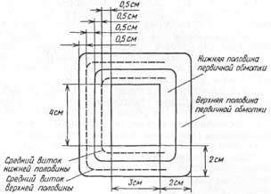
If we wanted to use such a transformer in a modern amplifier, where the lower limit of the operating range is 20 Hz, then at this frequency the signal loss would already reach 70%, i.e. a signal with a frequency of 20 Hz could not be reproduced at all. So what should be done to solve this problem? The answer is obvious: it is necessary to increase the inductance of the primary winding and at the same time reduce its active resistance. It is possible to increase the inductance by increasing the number of turns of the winding and reducing the losses in the magnetic circuit of the transformer. But with an increase in the number of turns, the active resistance of the winding also increases, and we need it to decrease. There is only one way to reduce the winding resistance with an increase in the number of its turns - by increasing the cross section (diameter) of the winding wire, but then more space will be required to place the winding on the frame, and this will entail an increase in the overall dimensions of the transformer. What real values of the inductance of the primary winding and its active resistance can be considered acceptable for modern UHF with a lower bandwidth limit of 20 Hz? If we set the maximum allowable value of signal loss at the lower frequency of the range of 10%, then the calculations will give L = 40 H at r = 500 Ohm XL \u2d 6,28 pfL \u20d 40 x 5 x 0,5 \u0,1d XNUMX kOhm; r = XNUMX kOhm; r = XNUMXXL. The constructive calculation of such a "theoretical" transformer, taking into account the fact that for a push-pull circuit there should be two primary windings, and not one, gives a value of 1500 ... 2500 turns of PEL or PEV wire with a diameter (for copper!) 0,44 ... 0,51 .50 mm for the primary winding and 150 ... 0,8 turns of wire with a diameter of 1,2 ... 20 mm for the secondary. In order for these windings to be placed on the frame, the size of its window should be approximately 50x10 mm, which leads to the need to use a transformer with a magnetic circuit cross section of at least 12 ... 10 cm with an amplifier output power of only 15 ... 40 W. For amplifiers with an output power of 15 W, the cross section increases accordingly to 18 ... XNUMX cm. For comparison, we recall that such a package of iron (section 30x63 mm) had ... a power transformer of the Rubin-102 TV with a power of 150 W! This is the price today for the real lower end of the 20 Hz amplifier bandwidth. Now let's talk about the price of another indicator - the non-identity of these two halves of the primary winding, wound by the traditional, invariably used in industrial production method - one on the other. Let's take a closer look at the section of the coil frame of the output transformer, shown in Fig. 52. At first, one half of the primary winding was wound on the frame, then one or several layers of insulation followed, and after it the second half of the winding was wound (to simplify the picture, we will not take into account the presence of the secondary winding). At the same time, it is quite obvious that the length of the first turn (at the base of the frame) was significantly less than the length of the last turn of the second half of the winding. However, the word "significantly" in this case is unacceptable: we are interested in the quantitative side of the issue. To begin with, in order not to load the reader with cumbersome calculations, let us turn to the simplest arithmetic-geometric calculations. It can be seen from the figure that the length of the very first (inner) turn is 4+3+4+3=14 cm, and the last (outer) - 7+8+7+8=30 cm. However, we are not interested in the lengths of the two extreme turns, but the comparative lengths of the middle turns in the first and second halves of the winding, since they are directly proportional to the values of the active resistances of these two halves. From the same figure it can be seen that they will be l1 = 4+5+4+5 = 18 cm and I2 = 6+7+6+7 = = 26 cm. Since the entire winding is wound with the same wire, the ratio of the active resistances of the two its halves will be the same, i.e. with a total resistance of 500 ohms, the lower half will have a resistance of r1 = 200 ohms, and the upper half will have a resistance of r2 = 300 ohms.
Once again, we will make a reservation that this calculation is quite approximate, but even it leads to the following result: if two triodes with an anode current of 100 mA each are used in the final stage at a source voltage of 120 V (for example, 6S19P lamps), then as a result voltage drop on the constant active resistance of the windings U1=Ia*r1=0,1x200=20B; U2=Iar2=0,lx300=30B 120 - 20 \u100d XNUMX V will remain on the anode of the first lamp, and on the anodesecond -120-30 = 90 V. Thus, with the classical method of winding the transformer and the absolute equality of the number of turns of the two halves of the primary winding, the voltages at the anodes of the two terminal lamps will differ by 10%, which, of course, will exclude the possibility of obtaining nonlinear distortions within 1%. This is the price of the "classic" winding technology of the output transformer. To this it should be added that the inductances of both halves of the winding will not be the same, since the formula for the inductance of a multilayer cylindrical coil includes the diameters of the lower and upper turns, and they will turn out to be different for the two halves of the winding. But forwhy do we consider all these issues in such detail, instead of just giving specific design and winding data of transformers? With the sole purpose: firstly, so that the radio amateur understands that the requirements for the design of transformers, which he will face in the future, are by no means unjustified or excessive, and, secondly, so that in the manufacture of transformers he steadily follows our instructions and recommendations . Let's move on to the practical side of things. Let's start by choosing the type of magnetic core for the output transformers. From the point of view of the quality of the transformer's operation, the shape of its iron magnetic circuit is not significant, but from the standpoint of the convenience of winding, it is better to use O-shaped tape split rod-type magnetic circuits. In this case, two absolutely identical frames with two absolutely identical windings are placed on each of the two rods, which in principle eliminates the difference in the electrical data of these windings. The winding of each of the two coils in this case does not require any special actions and is carried out on a conventional winding machine with a "carrier" (coil stacker) and a counter for the exact number of turns, which makes it possible to carry out dense ordinary layer-by-layer winding "coil to coil". It is unacceptable to wind coils in bulk. Over the half of the primary winding on each of the two coils, half the turns of the secondary winding are wound in the same way, and after assembling the transformer, both halves of both the primary and secondary windings are connected in series. Such a transformer is ideal in terms of the complete identity of the symmetrical parts of its windings and has negligible external stray fields. Can make a good output transformer andonlaminated armored magnetic circuit from individual W-shaped plates, however, its manufacture is more laborious and requires additional operations. The first difficulty is connected with the magnetic circuit itself. First of all, it must be taken into account that plates with a thickness of 0,5 mm are unsuitable for our purposes. The maximum allowable thickness is 0,35 mm, and if the iron is 0,2 mm, even better. Having assembled a package of the required thickness, you should add at least 10% of additional reserve plates (and jumpers) to it in reserve. All plates and jumpers must be coated on both sides with a spray gun with any nitro-paint or liquid zaponlak, and then dried thoroughly (in the air, in the sun or in the oven). This measure is needed to minimize the losses in the magnetic core due to Foucault currents. After that, each plate and jumper must be examined for the absence of burrs and notches on them, which, during the assembly of the package, can break (scratch) the protective layer of varnish or paint. Detected defects can be eliminated with a needle file, a fine emery wheel or a knife. It is even better to replace defective plates from among the reserve ones. The next problem is the partitioned frame. Most likely, none of the industrial ones will suit you, especially if it is non-separable. But before you start making the frame yourself, you need to stop at one of the three winding options shown in fig. 53. Option "a" assumes the presence of a frame, divided exactly in half by an additional inner cheek for the entire height of the window. In this case, one half of the primary winding is wound in each section, on top of which, after several layers of insulation (cable paper or varnished cloth), exactly half of the turns of the secondary winding are laid in each section. The sections of the primary and secondary windings (of course, apart) are connected in series.
In option "b", the middle cheek is made of a smaller height - flush with the halves of the primary winding. After their winding, two or three layers of cable paper insulation are laid over the entire width of the frame, and from above, also over the entire width of the frame, the entire secondary winding is wound without breaking. And finally, option c provides for the breakdown of the frame into three identical sections. In the two extreme sections, halves of the primary winding are wound, and in the middle section, the entire secondary winding. From an electrical point of view, all three options are equivalent, so the designer can choose any of them. The plates of the magnetic circuit are assembled end-to-end, without a gap, since there is no DC bias in push-pull circuits. It is desirable to subject the assembled transformer to moisture-proof treatment, which is quite simple to implement at home. To do this, in an iron can from canned food or any other similar utensil (saucepan, bowl), inside which the output transformer can fit in whole or at least partially, you need to melt and warm up the wax, paraffin, stearin or industrial ceresin well. The transformer is lowered into the jar and kept in it for 2...3 minutes, continuously heating the melt. After complete cooling (to room temperature), frozen drips, if they interfere with the fastening of the transformer, can be carefully removed with a wooden or plastic spatula (but not with a steel knife!). If possible, it is advisable to place the finished transformer in a solid metal casing-screen before installation on the chassis. This must be done to exclude the effect of its electric and magnetic fields. on lamps, exposed printed wiring, op- erators and connecting wires, and thereby prevent the occurrence of uncontrolled parasitic feedbacks. Next, we will give the design data of the magnetic circuits and the electrical data of the windings for all the amplifiers described in the book, as well as the winding data of the recommended power transformers and filter chokes. However, we immediately warn that the exact repetition of the given data with an accuracy of one turn and the use of the recommended diameters of the winding wire is not always optimal, and in some cases may lead to the fact that all the windings will not fit in the frame window. The fact is that the packages of magnetic circuits used by radio amateurs can vary greatly, sometimes several times, among themselves in the quality of transformer steel, which leads to different inductances with absolutely the same number of coil turns, and, consequently, to a non-optimal mode of the terminal lamps in terms of the undistorted output power. The window filling factor with windings also depends on many data: on the type of winding wires used (PE, PEL, PEV-1, PEV-2, etc.), having the same copper diameter (for example, 0,2 mm ) real outer diameters from 0,215 to 0,235 mm; on the type and thickness of insulation between layers and windings (cigarette, capacitor, cable paper, varnished cloth, coated paper, drawing paper); on the number of layers of such insulation; on the density of winding and the degree of tension of the wire; on the completeness of filling each layer of winding with turns and a number of other factors. Some important tips: 1. Choose magnetic cores made of high quality transformer steel grades. 2. When winding the winding, make two or three taps at its beginning or end in increments of 5% of the total number of turns. This makes it possible, if necessary, to select the most optimal number of turns. 3. Wind the windings only in an ordinary way, tightly laying a turn to a turn from the cheek to the cheek of the frame, leaving no empty spaces at the edges. 4. Be sure to make an insulating pad of thin (cigarette or capacitor) paper after each layer of winding so that the turns of the next row do not fall near the cheeks of the frame into the lower layers. 5. Avoid using winding wires with a larger diameter than indicated in the description. Otherwise, the windings may not fit in the frame window and the transformer will have to be rewound. Keep in mind that using a slightly smaller diameter wire will not noticeably affect the parameters of the amplifier, but it will ensure that all the windings fit in the frame window. Literature 1. High quality tube ultrasonic frequencies Author: tolik777 (aka Viper); Publication: cxem.net
Machine for thinning flowers in gardens
02.05.2024 Advanced Infrared Microscope
02.05.2024 Air trap for insects
01.05.2024
▪ Smart umbrellas will replace meteorologists ▪ Accurate frost forecast with AI ▪ Computer mouse without borders ▪ Ultra-strong aluminum alloy created ▪ Sweet sodas make people dumb
▪ section of the site Winged words, phraseological units. Selection of articles ▪ article Send from Pontius to Pilate. Popular expression ▪ article How do antibiotics work? Detailed answer ▪ Article Hyssop vulgaris. Legends, cultivation, methods of application
Home page | Library | Articles | Website map | Site Reviews
www.diagram.com.ua |


 Leave your comment on this article: